Over the years, I've been asked a lot of questions about Fly Baby wing bracing. This is an attempt to provide builders and owners a background into how the Fly Baby works. It's a compendium of earlier writeups and of new material.
Before we get going, let me remind folks that 1) I am not the designer of the Fly Baby, nor do I speak for him; 2) I am not a licensed Professional Engineer and am not qualified to make engineering judgments regarding this or any other aircraft; and 3) While I fly a Fly Baby, I have not built one myself. This article is just an attempt to provide a layman's description about how things work on a Fly Baby.
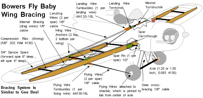
To start with, let's take care of a little basic terminology. There are two primary types of bracing wires on the Fly Baby: Landing and Flying wires. Landing wires attach to the top of the wings, Flying wires attach at the bottom.
So the next question is: What holds the Fly Baby's wings on when the plane is in the air?
The answer is more complex than you think. The wing support structure includes the landing gear Vees, the axle, and BOTH the landing and flying wires.
If you follow one set of flying wires out from one wheel hub, you'll see the loads go into the bottom of the wing, then out the top via the Landing wire. The load crosses the cockpit via the Master Turnbuckle, down the Landing wires and the Flying wires on the opposite wing, then across the axle to the wheel hub where we started the process. I call it a "closed-loop" bracing system.
Think of when you were a kid, and wanted to build a tire swing. You could climb a tree, tie one end of a rope on a limb, then climb back down and tie the other end of the rope to the tire. Or...you could tie one end of a long rope to the tire, throw the other end of the rope over the limb, and tie it to the tire as well. It's a lot easier to do, and just as strong as the first method.
The Fly Baby bracing concept is similar. However, just like the tree is essentially immovable, the Fly Baby needs a rigid section to anchor its bracing. That's where the landing gear comes in. The gear is composed of the most effective structural element: Triangles. The gear legs, the axle, and the bracing wires all combine to produce a rigid base for the rest of the rigging.
So: It's all important. Like on all
homebuilts, the
wing structure must be properly built and properly
maintained. On
the Fly Baby, this includes the landing gear, the landing and
flying wires,
the wing spars, and all the small bits that are associated with
them.
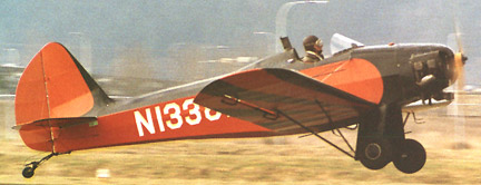
Of course, there are are total of eight flying wires under the two wings (remember, the "flying wires" are the ones UNDER the wing; they support the aircraft weight in flight). Since a single wire can support more than 150% of the Fly Baby's total weight, eight of them must give the plane a heck of a G-capability, right?
Sadly, that's untrue. If you look at the Fly Baby, you'll see the flying wires attach to the bottom of the wing at a rather steep angle. Here's a simplified sketch:
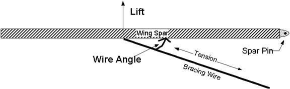
So, let's take a look at Fly Baby. Let's assume a 925 pound airplane, with stock cables rated at 1600 pounds. How many "G"s is it good for? In this case, we're going to turn the above equation around, and solve for the Force (lift). The equation is now Force = Tension x Sin (Angle).
Ah, there's one thing we forgot: We've got eight flying wires. So the equation now becomes:
Force = Number of Wires x Tension x Sin(Angle)
To get the Gs this is equal to, we just divide by the aircraft's gross weight.
G = N x T x Sin (Angle) /Gross Weight
The angle is about 30 degrees, the number of wires is eight, and the maximum allowed tension is 1600 pounds. Our formula becomes 8 x 1600 x Sin (30 degrees) which comes out to 6400 pounds. Divide by the gross weight of the aircraft (1000 pounds) and we learn that the stock wire system is theoretically capable of 6400/925 or 6.9 Gs.
Alas, things aren't this simple. The four bracing wires on each wing attach two to each spar...and the weight isn't evenly distributed between these spars. I'm told that, at high G loading, the center of pressure shifts aft and DOES tend to equalize the loading between the two pairs of flying wires per wing. Pete says the forward wires take 60% of the level-flight load. We'll assume four flying wires (just the two forward pairs) and assume they're supporting 60% of the total gross weight: G = 4 x 1600 x Sin(30) /(0.6 x 925) or 5.7 Gs.
If you look on page 8-33 of your plans, you'll see a Finnish Fly Baby, upside down, with 5286 pounds on his wing...a weight corresponding to about 5.71 Gs. This was performed in front of government representatives, and there was no damage to the aircraft. 5.7 Gs is equal to the ultimate limit for Normal category.
This assumes, of course, that the tension in the wires are properly adjusted. The next two sections cover this issue.
The basic answer is: Bowers doesn't specify a tension value. It is more important to make sure the pairs of flying wires are evenly tightened than to try hit a particular amount of tension.
Why is it done this way? Well, one of the design criteria of the original EAA contest is that the wings be foldable. Pete Bowers didn't want the pilot to have to completely re-rig the airplane when the wings were unfolded, so he designed it so that the individual wires join at shackles or steel terminals. The Master Turnbuckle is then used to tighten all the wires at once.
Strange as it seems, though, that's NOT how it works. I
asked
my mechanical engineer buddies to give me a good analogy as to
"why," and
this is what we came up with.
| Let's assume you put a hook on the ceiling. Below it is a shelf solidly attached to the wall, with a little hole in it to pass a cable through. You put a weight scale on the ceiling hook, then attach a turnbuckle below it, with the cable dropping through the hole and attached to a weight hook below. The Scale reads essentially zero at this point; just the weight of the turnbuckle, cable, and hook. | As you tighten up the turnbuckle, the scale still shows essentially zero until the top of the hook contacts the bottom of the shelf. If you then keep tightening the turnbuckle, the scale starts reading higher. You're putting "preload" into the cable. The cable is actually stretching a little bit as it gets tighter. Let's assume we stop tightening when the "preload" gets to 100 pounds. | Now: Add a 200-pound weight to the
hook. Does
the scale read 300 pounds (100+200) or the actual
weight?
When the weight was added, the cable stretched enough so that the hook was no longer against the bottom of the shelf. All the scale sees now is the 200 pound weight. |
 |
 |
 |
It still reads 100 pounds. It behaves like there has been no change in the total system tension.
Metal fatigue happens when the load on a material is cycled..if it's loaded and released, loaded and released, over and over again. With preload in a system, the cable and turnbuckle don't see that cycle. All they see is one tension all the time...so metal fatigue never gets a start.
When you work on an engine, the engine manufacturer specifies the
amount
of torque that should be applied to the bolts when the parts are
reassembled.
What you're doing is the same thing as adjusting the turnbuckles
on a Fly
Baby: You're setting the amount of preload in the bolts so
they don't
fail through metal fatigue.
That's a lot of tension. If Pete had tried to do it with a single wire per spar, that would have been a pretty hefty wire, and a pretty big turnbuckle. That kind of gear is really expensive, and few people have the tools to put fittings on 3/8" cable.
Instead, Pete used a traditional aircraft system: He used pairs of wires to the spars. Ordinary 1/8" cable would suffice, as well as 1600-pound turnbuckles.
There is one drawback: It's important that the two wires each bear the same load. If one gets a higher load, it'll break first...and the sudden jerk will break the other one, as well. So it's important to set the each pair of wires at the same tension relative to each other.
You don't have to worry about whether the flying wires on the left wing are the same tension as those on the right. The Fly Baby's closed-loop bracing system will equalize those in flight. Nor do you have to worry about getting the aft pair at the same tension as the front pair. The difference in tension between the forward and the aft wire pairs is what sets the wing's washout in flight. Changing the tension of the aft pair is how you solve wing-heaviness problems.
But it's vital to get the two wires in each pair to an equal preload. Normally, cables are tightened while monitoring a tensiometer. Back when the Fly Baby was designed, though, Tensiometers were rare and expensive. Pete came up with a way to get the tensions approximately equal without one. You'll find it on page 8-10 of your plans. Basically, Bowers' instructions are to run the Master Turnbuckle all the way until the shoulders of the landing wire terminals come up against their fittings. Then, gradually tighten all the turnbuckles by hand until they can no longer be turned. Next evenly tighten the turnbuckles two turns each using a nail as leverage. Then safety-wire the individual turnbuckles.
This system has worked reliably for forty years. It wasn't until the year 2000 that a Fly Baby accident was attributed to unequal flying-wire tension, and this airplane had been bought for parts and flown without an inspection.
However, one thing has changed since the Fly Baby was designed: Low-cost cable tensiometers have become available. You can buy a nice one for about $130, or a fairly cheap model for about $40.
Note that, again, raw accuracy is not required. It's not important whether the cheap gauge is off by 5 pounds in tension, as long as the reading is repeatable. If you put the tensiometer on the wire, take it off, and put it on again, it should read the same. If it doesn't, you've either messed up the attachment process or the gauge lacks sufficient repeatability.
I bought the mid-price tensiometer in June 2001. Here's my
report
to the Fly Baby list about adjusting my wires:
---------------------------------------------------------------------------------------------------------------------------
First off, my airplane is atypical. It has three flying
wires
on the forward fitting. I don't care for it (it makes
balancing
that much more difficult, and I think it makes it MORE sensitive
to balancing)
but that's the way it is.
Second, the gauge is not precisely marked. It's marked in 10-pound increments from 10 to 70. At the higher part of the scale, the numbers are pretty close together. I estimated the actual reading when it fell between markings. Before logging the reading, I rocked the scale back and forth to get a feeling for the range the thing might indicate.
To start with, I knew my Master Turnbuckle was a bit slack.
I
took a reading with the original setting (all numbers are in
pounds):
|
|
Left Wing | Right Wing |
| Forward Front |
|
|
| Forward Middle |
|
|
|
|
|
|
|
|
|
|
| Aft Front |
|
|
| Aft Back |
|
|
I was curious about the difference between the left and right wings. It seems to me they SHOULD be about equal. Still, there's probably quite a bit of friction in the system, and without being loaded, the tension probably isn't balanced. I shook the wings up and down to try to slide things around, and retested. I got about the same readings.
After this reading, I cranked on the Master Turnbuckle with an Allen Wrench to give me leverage (~3 inches long). I tightened it one turn.
|
|
Left Wing | Right Wing |
| Forward Front |
|
|
| Forward Middle |
|
|
|
|
|
|
|
|
|
|
| Aft Front |
|
|
| Aft Back |
|
|
I decided to see how tight it would actually go. Normally, I have to rotate the turnbuckle in half-turn increments so the safety screw will go through it (I have a long screw running down into the wood of the shelf to keep the Master Turnbuckle from self-rotating). I managed to turn it another quarter-turn:
|
|
Left Wing | Right Wing |
| Forward Front |
|
|
| Forward Middle |
|
|
|
|
|
|
|
|
|
|
| Aft Front |
|
|
| Aft Back |
|
|
Interesting. The main effect of the tightening IS on the cable that's already the tightest. And it doesn't have a whole lot of effect on the aft cables.
In any case, it's obvious that my plane has been doing fine, even with the unequal tension in the cables. I backed off the Master Turnbuckle to a position that'd let me put the safety screw in, then went to work on the individual turnbuckles.
My starting tensions on the Right wing were:
|
|
Right Wing |
| Forward Front |
|
| Forward Middle |
|
|
|
|
|
|
|
| Aft Front |
|
| Aft Back |
|
I took the safety wire off the Front and Middle ones, and tweaked them both up to approximately 45 pounds. It was tough...get one a smidge too tight, and the tension on the other two would drop steeply. My final results were about 42, 44, and 40 pounds. Within 5% is probably pretty good.
The aft wires on that side were pretty matched, so I didn't touch them. My plane flies a bit left-wing heavy; I may end up backing off on them (equally, of course) to reduce the angle of incidence on that wing.
Time for the Left wing. Starting tensions were:
|
|
Left Wing |
| Forward Front |
|
| Forward Middle |
|
|
|
|
|
|
|
| Aft Front |
|
| Aft Back |
|
In this case, I chose to back off the tension in the Back wire of the forward set. By the time I was done, the tensions were all running between 45 and 50 pounds.
As I mentioned in the write-up, the left wing was a bit heavy before the adjustment. When I balanced the aft wires on the left side, I brought the front one up to match the back one. This would have the effect of slightly increasing the total tension for the back pair.
The next time I flew, I was pleasantly surprised: The wing heaviness was almost completely gone.
It was a relatively short procedure...it really didn't take much
time
at all. More time was spent re-safetying the turnbuckles
than in
the actual adjustments. Once you adjust one of the pair to a
target
value, don't forget to recheck the other one...it will likely have
changed.
You have to go back and forth between the two to get them balanced
up.
On the surface, this seems like an ideal solution. A quarter-inch solid tie rod is stronger than two cable assemblies using -16 turnbuckles...a LOT stronger, if a round rod is used instead of a streamlined one. The only apparent drawback is cost...these things are pretty expensive.
 However, there
is an insidious problem here: the solid rods seem to
vibrate, and
the vibrations have led to cracking of the wing anchor
plates. In
May 1999, a solid-rod-equipped Fly Baby had one of the wing plates
fail
in flight. The NTSB report traced the problem to vibration
cracking.
Fortunately, the owner, Scott Hinton had been wearing a parachute
and successfully
bailed out. I discuss this accident in a report
on my web page.
However, there
is an insidious problem here: the solid rods seem to
vibrate, and
the vibrations have led to cracking of the wing anchor
plates. In
May 1999, a solid-rod-equipped Fly Baby had one of the wing plates
fail
in flight. The NTSB report traced the problem to vibration
cracking.
Fortunately, the owner, Scott Hinton had been wearing a parachute
and successfully
bailed out. I discuss this accident in a report
on my web page.
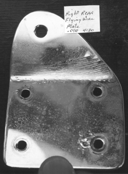
Also, Cliff Phillips had solid rods on his airplane...and chrome plated wing anchors. He replaced the tie rods with stranded cable when he noticed the stress patterns appearing in his anchor plates...Check out the picture. He also reported actually feeling the vibration in flight. At the time these pictures were taken, his plane had only 53 hours on it. By the way, people I've talked to say not to chrome-plate structural parts like the anchors....
The solid tie rods are usually used in biplanes. Unlike on a Fly Baby, the landing and flying wires on biplanes cross. Designers tie the rods together at these crossing points, and the "X" configuration damps out vibrations on both the landing and flying wires. There's no wire crossing on a monoplane design, so we don't have as good a situation for killing the vibration. On both biplanes and the Fly Baby, you usually see an "arrow" tying together the rods/cables about half-way between their attachment points. Tying the wires together tends to dampen vibrations in any one of them. A stock Fly Baby has four wires tied by an arrow, but a Fly Baby with solid rods only connects two widely-spaced rods.
 I
keep my Fly
Baby in a hangar next to one of the two original Story Specials, a
plane
very similar to a Fly Baby, only with a welded-steel fuselage and
tie-rod
bracing. The problem is, the Story taxis home occasionally
dragging
a broken wire behind it. They are, essentially, stiff components,
and vibration
will fatigue them. When they break, they seem to separate about
where the
threads start. Fortunately, the Story uses four tie-rods per side
(In the
picture, each pair is faired together with aluminum, which is why
it looks
like there are only two). But there's certainly vibration
going on
there.
I
keep my Fly
Baby in a hangar next to one of the two original Story Specials, a
plane
very similar to a Fly Baby, only with a welded-steel fuselage and
tie-rod
bracing. The problem is, the Story taxis home occasionally
dragging
a broken wire behind it. They are, essentially, stiff components,
and vibration
will fatigue them. When they break, they seem to separate about
where the
threads start. Fortunately, the Story uses four tie-rods per side
(In the
picture, each pair is faired together with aluminum, which is why
it looks
like there are only two). But there's certainly vibration
going on
there.
While I'm not a structural or aeronautical engineer, I'm real skittish about the potential for solid tie rods or streamline rods to cause vibration problems in Fly Babies. I think the stranded construction of the regular cables probably damps out a lot of vibration. I also wonder if the "slip-joint" connection between the cable thimble and the turnbuckle also damps out vibrations that would otherwise be placed into the wing anchor plate.
While I have no "official" standing in the Fly Baby world, I really recommend people stick with the stock cable-and-turnbuckle system.
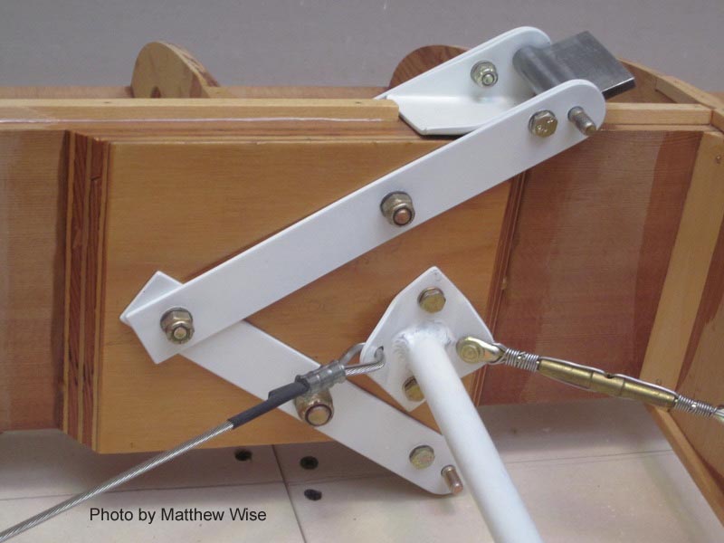 However, there
are other ways of handling the flying and landing wire attachment
to the
wing. When EAA Chapter 26 rebuilt Pete's prototype in 1982, they
switched
to one of Pete's alternate wire-attachment systems. In this case,
four
flat strips of steel are bolted diagonally to the spar, jutting
above and
below the wing. The flying and landing wires bolt directly to
these strips
rather than to the anchor plate.
However, there
are other ways of handling the flying and landing wire attachment
to the
wing. When EAA Chapter 26 rebuilt Pete's prototype in 1982, they
switched
to one of Pete's alternate wire-attachment systems. In this case,
four
flat strips of steel are bolted diagonally to the spar, jutting
above and
below the wing. The flying and landing wires bolt directly to
these strips
rather than to the anchor plate.
This drawing is included on Figure 4-2A on your plans (it's the fold-out with the Rib web).
The drawing shows a little bended tab between the small plates for attaching the turnbuckles to. In all honesty, I don't think N500F had this tab...it just bolted one turnbuckle to each plate. I don't know if N500F's had the welded reinforcement between the straps, as shown in the drawing.
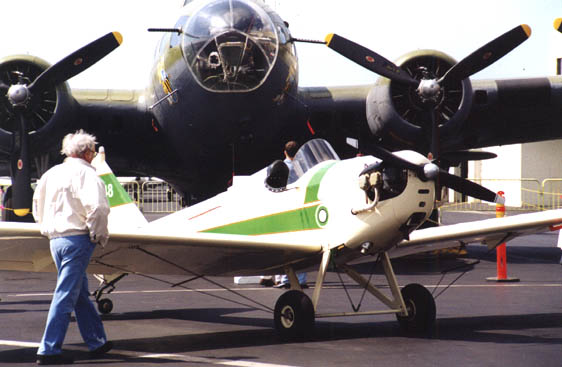 I
started to answer,
"I do, and so does everyone else," but when I paged through the
pictures
on my web page, I realized that not everyone was carrying
them. Most
were, but I saw a couple of guys who don't have them. You
can see
mine below the wings in this picture:
I
started to answer,
"I do, and so does everyone else," but when I paged through the
pictures
on my web page, I realized that not everyone was carrying
them. Most
were, but I saw a couple of guys who don't have them. You
can see
mine below the wings in this picture:
Before I go to much further, I want to reassure folks: I don't think they're critical. I think they're a good idea, but the monoplane configuration doesn't allow the same advantages as the biplanes get.
When the "Arrows" are added to the wires of a biplane, they're located right at the "X" intersection of the sets of bracing wires. Since the wires meet an an angle, joining them can greatly reduce any shaking of the wires.
On a Fly Baby, though, the wires don't cross. The Arrows can only join the four wires in a single plane. I believe that attaching the arrows across the wires does damp out vibration to some extent...though whether the fatigue difference is significant, I have no idea.
The nice thing about Arrows is that they're VERY easy to implement. Go to a sporting goods store, and buy four arrows of appropriate length and color. Lay one across a set of flying or landing wires about halfway out, then use ty-wraps or safety wire to fasten the arrow to all four wires.
You can cut off the point and the feathers.... or not. If you're really feeling cheap, buy some ~3/8" hardwood doweling and make your own. The guy who made my Fly Baby went overboard on the arrows, like he did on everything else. Mine have slots in them, and the arrows are actually split down the middle, with the halves held together by allen screws. I kid you not. But the cheap doweling works just as well.
By the way, the Story Special's arrows have a large stabilizing fin at the tail. But only on the landing-wires...not on the flying wires. I asked the guy in charge of the club why he only put them on the top wires, and he said, "'Cause I can't SEE the bottom ones!" Out of sight, out of mind... :-)
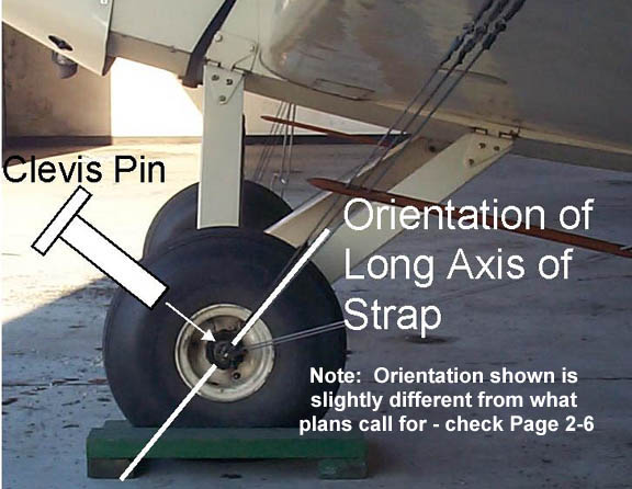
Think about how the load is transmitted to the strap. Think of it like a popsicle stick: If you hold the stick flat and push up on it, it'll break pretty quickly. But...if you hold the stick with vertically and push up, it's resists a lot better.
The same holds true with the flying-wire attachment anchor strap. According to pages 2-6 and 2-9 of the plans, "To accommodate the wing wires, the anchors should install so that their long edges are parallel to the rear legs of the vees."
Oddly enough, when I checked my own Fly Baby, I found the
orientation
a few degrees off. The strap is doing fine, though.
This picture
will give you an idea of the proper setting.