Initially, I was going to install one leg of the copper-tape dipole down the back of my brand-new gear leg. However, being a good Systems Engineer,* I kept foreseeing problems with durability. The gear-leg dipole would be connected to the interior of the aircraft by a thin wire exposed to the prop blast and passing through a drumming fabric covering, and the other would be attached to the drumming fabric itself. In addition, installation would require me to practically stand on my head in the narrow cockpit to put the antenna hardware near the floor.
(* A Systems Engineer is someone who loses sleep wondering if "Anal Retentive" should be hyphenated.)
If I were building my Fly Baby, I'd install copper-tape dipoles. My Fly Baby has dipoles made of the coax itself; they worked fine for almost twenty years. But one had obviously developed problems; I needed a design that was durable and didn't require a contortionist to install.
A couple of things worked in my favor. First, Jim Weir had sent me his publication on antenna design ("RST-802 Antenna Reference Text," available at a fine www.rst-engr.com near you). It's primarily an aid to building copper tape antennas, but there was plenty of general information in there to help me along. Second, I recently escaped a sterile orbit-analysis job for one with a company that actually BUILDING something. I've got a never-used EE degree, and the daily whiff of hot solder coming from the prototype labs was like gunpowder to an old war-horse. I wanted to BUILD something! Plus, my new job has a full lineup of RF design engineers quite willing to discuss antennas.
Third, I had the design of the Fly Baby working in my favor. The wood is mostly transparent to an antenna, so I could mount it internal to the aircraft. The two existing antennas, in fact, are dipoles installed along the top longerons on either side of the fuselage.
So: Time to get designing.
Unless I went with a dipole, I would need a ground plane of some sort. There are few places on the airplane that provide enough sheet metal for a ground plane. The forward fuselage is one possibility, but the only metal on the bottom of the plane is a removable inspection panel ~2 feet wide and about 15 inches long. Probably make a good ground plane, but I'd either have to disconnect and reconnect the antenna every time I took the panel off, or I'd have to mount the base internally and trim the inspection panel to pass the antenna rod. I wanted to avoid this approach; besides, the forward mounting location would put the antenna close to the heavy steel of the wheel axle, which would distort the signal.
The turtledeck aft of the pilot seat is metal for about 30 inches. A beautiful ground plane, really. But the turtle deck is removable; again, I'd have to connect and disconnect the antenna every time. Plus, my cockpit cover extends pretty far aft...I'd have to mount the antenna further aft than optional or modify my cockpit cover.
Plus...well, IMHO, external antennas are ugly. I have a wooden airplane; I wanted to take advantage of it.
I had a roll of Jim's copper tape as a start, so I wandered over to Home Base Aerospace to try find some hardware that could hold a strip of his tape at the appropriate angle. I'd hoped I could find something in the plumbing department, and hit jackpot right away. The 1/2" plastic pipe had a unit called a "Wing Elbow." This was an elbow design to mount flat to the wall; water could be fed vertically, then the elbow turns it to come straight out from the wall. Couldn't have been DESIGNED better for my purpose.
In his antenna reference, Jim mentions some people having problems with the plastic plumbing pipe. Thinwall white PVC is OK, but while he himself hasn't had any problems with the gray or black stuff, other people have.
The half-inch fittings WEREN'T PVC, though. They were listed as some other formulation...PCVC, or some such. Light beige in color. Oh, well, the only thing to do was try.
After a few minutes staring at the fitting samples, I mentally had the design for a copper tape antenna that was essentially half one of Jim Weir's dipole designs; the "Semi-Weir'd," I dubbed it. The BNC connector would go to the outlet parallel to the mounting flange, and the second outlet (facing straight down) would get a 45-degree elbow. Into that elbow would go a section of the 1/2" tubing with the appropriate length of copper tape inside. I'd flute the tubing like a machine gun barrel to reduce weight. A short piece of wire on a ring terminal would bring the shield side of the BNC connector to the mounting flange of the elbow for connection to the ground plane. The Elbow cost about 75 cents each, the caps were a quarter, and I think a 6' piece of pipe cost about two bucks.
Now, on to the local Electron Hut for the electronic half of the design. I needed BNC panel jacks, and connectors for the coax, and...
The BNC hardware was mounted with the CB stuff. Thoughts of the Semi-Weir'd antenna faded as I scanned the CB antenna accessories. Somehow, SOMEWAY, it had to be possible to adapt some of that lovely hardware to work on aircraft. Prices weren't bad, either. Here was a telescoping scanner antenna with a BNC connector built in. Here was an antenna mount for a car window, a J-shaped piece of metal. Here was a replacement CB whip antenna, for all of $7.
I ended spending another 25 bucks, but now had material for building two additional antenna styles.
The telescoping scanner antenna intrigued me the most. It wouldn't work as constituted. But, with a BNC panel connector, I'd be able to attach the antenna to ONE side of the connector, and the coax to another. No electrical work at all (other than installing the BNC connector on the coax). All I needed was a strip of aluminum say, 1/8" thick, about an inch wide. Bend the end down at a 45-degree angle, drill a hole for panel connector, and the scanner antenna would be pointing down at 45 degrees just like I wanted it.
But the scanner antenna itself wouldn't do. Not only did I NOT want a telescoping unit, it included a loading coil near the tip. I cut off the whole telescoping part, leaving just the BNC connector with a six-inch stub of antenna tubing. The ID of the tubing was about 5/16". Jim's reference discussed using brass as an antenna element, and thus the "Half-Brassed" antenna design was born: I trotted off to the hobby store, and bought a 30" section of 5/16" .014" wall brass tubing.
However, connecting the brass tubing to the antenna stub was an issue. The stub appeared to be stainless steel, and I knew I couldn't solder the brass to it. I used pulled rivets to hold the two parts together, and I drilled a small hole in the stainless steel tube and put a good hot solder drop against the brass tube exposed underneath. Still, I was worried about durability...ten years from now, would the electrical connection fail? One of the RF experts at work offered to silver-braze it, but I was stubborn: I didn't want to require any outside help. Plus, I couldn't seem to find the BNC-to-BNC panel connector I needed. Electron Hut didn't carry them, and neither did the small electronics supply house down the street. A store up North probably had them, but that would require a separate trip.
[Post-Script: I found the connector. However, when fiddling with this antenna in my workshop, the nylon in the BNC connector built onto the antenna broke. I don't think it's sturdy enough for my needs.... RJW 15 June 2001]
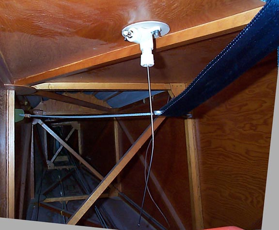
Fortunately, a third concept rose to the fore, one that seemed to be the best (and quickest solution). "CW McCall's Revenge" used the $7 replacement whip antenna. It came with a small mounting base, consisting of a 1/4" wide threaded section with a set-screw holder for the whip itself. All I needed to do was mount the base inside the elbow and run the whip straight out the end.
How to hold the base inside the elbow? A nut plate, obviously. Rather than picking up an aircraft-quality quarter-inch nut plate, I decided to use a T-Nut available at Home Base Aerospace for about a buck. I drilled a hole through the flange end of the wing elbow large enough to pass the threaded section of the T-nut. Drop the T-Nut into the hole, and rivet/epoxy the flange.
How to connect the center conductor? Well a short piece of wire soldered to the BNC connector of the proper length to put a ring terminal dead-center over the hole in the T-nut. Install the BNC connector in a pipe cap, use a short section of pipe to work the interface, and glue the assembly in place.
Drop a washer and a lock washer down the remaining opening of the elbow, then screw the antenna base down. I actually shortened that leg of the elbow a bit before installing the base, so that the set screw for holding the whip was accessible. Cut the whip down to about 23 inches, slide it into a hole drilled in another cap and a short section of tube, then slip the shank of the whip into the base and tighten the set-screw. Press the tube-cap combination in place, and the basic antenna was done.
Since the T-nut's flange now stuck out the bottom of the elbow's flange, the elbow would no longer sit flush. I cut out a small disk of 1/8" plywood and routed out the center to get everything sitting straight again.
I didn't want to be trying to handle locknuts blind under the shelf, so I decided to use anchor plates on the wing elbow. The anchors I had were too long to fit, so I trimmed a one-sided one down. I realized that an angle anchor plate would give me a connection lug for the grounding strap. I ran a wire from the BNC ground lug to the spare lug on the anchor plate. Now I had a unit that didn't need any wrench work or careful positioning under the baggage shelf.
So: To the aircraft.
I removed the turtledeck (10 seconds' work) and felt around underneath to locate the diagonal support for the shelf. Fortunately, the builder had marked the diagonal's location on the top the shelf. I positioned a spare wing elbow at a good spot, then drilled the two 3/16" holes for the mount. I held the antenna under the shelf, and noted how far it had to bend to clear the lower shelf. A quick bit of work with the pliers, and the antenna hung clear below. I turned it a bit off-axis to put the end well clear of the elevator cables on the bottom of the fuselage.
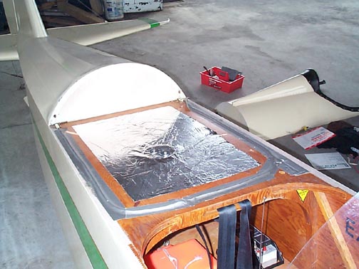 Ground
plane: I cleared off the top of the shelf, and applied a "Union Jack"
pattern of copper tape (despite it being St. Patty's day). I made
sure one leg of the Union Jack went right over the bolt holes. A
~4" disk of .040" aluminum, drilled for the mounting pattern, went atop
the Union Jack, then a broad sheet of aluminum foil, about 18" wide and
~24" long covered it all. I figured the face-up copper tape would
contact both the aluminum sheet and the foil. Punch through to open
the bolt holes, put a couple of big fender washers on a pair of mounting
bolts, then bolt the whole thing down.
Ground
plane: I cleared off the top of the shelf, and applied a "Union Jack"
pattern of copper tape (despite it being St. Patty's day). I made
sure one leg of the Union Jack went right over the bolt holes. A
~4" disk of .040" aluminum, drilled for the mounting pattern, went atop
the Union Jack, then a broad sheet of aluminum foil, about 18" wide and
~24" long covered it all. I figured the face-up copper tape would
contact both the aluminum sheet and the foil. Punch through to open
the bolt holes, put a couple of big fender washers on a pair of mounting
bolts, then bolt the whole thing down.
One of the difficulties I always have had with checking out the antennas on the airplane is the difficulty in reaching the connectors on the back of the radio. The Escort II is mounted between my shins, with the connectors almost to my ankles. The tight cockpit wouldn't let me bend over that far...even if I COULD bend over that far.
So: I'd put a short segment of coax to the radio, and use BNC connectors to hook on to the coax from the antenna. The local electrical supply store had had 3' segments of RG-58 ("Lan Cables") for less than two connectors would cost, and that three feet of length brought the ends just to the area next to the seat...perfect. I labeled each cable segment appropriately, then attached the antenna BNCs to the connector. I hooked my (previously good) receive antenna to the transmit side, and the new one to the receive side...I figured any gross antenna problem would then be noticeable.
I flew it last Saturday. There wasn't anyone I knew with a handheld about, but no one complained about my radio quality. The new antenna seemed to receive fine; I heard pattern calls from airports ~30 miles away. Other planes in the pattern were obviously waiting for my radio calls to complete before starting their own (one of my previous clues that my antenna was bad was lifting my finger off the mike button and often hearing someone half-way through their position call).
Well, it works...at least, it works in receive, which really only needed a coat-hanger. Time will tell, as far as durability is concerned. The Semi-Weir'd and Half-Brassed antennas are both sitting partially-completed on my workbench; I'll probably finish them as the mood strikes. With my installation, a complete antenna change will only take five minutes or so.
"CW McCall's Revenge," just adding up the pieces that went into that particular antenna, cost less than $20 including the connectors. The nice thing about it is that the coax connector is on the antenna side; there's no bulge atop my baggage shelf to get snagged by stuff or sat upon (I often sit on the shelf to work on my panel).
Well, in any case, I'm cured of my Antenna Madness. One of the funner diseases I've had this year. Sure beats Landing-Gear Lumbago...:-)
[Post-Post-Script: After about three months, still working fine.
I can receive radios from airplanes at airports fifty miles away...RJW
15 June 2001]
This may merely be a poor-workmanship issue on my part. But...the lug is big, and isn't really designed to be soldered to. The solder stayed stuck with the wire, and the whole wire came lose on the lug. It may be that the lug doesn't take solder well, and it's fairly hefty size means that one has to *really* heat it up to avoid a cold-solder joint like what I had.
I have decided to no longer depend on a solder connection to this lug I've added a conventional crimp-on terminal to the grounding wire and eliminated the anchor nut on one side. I now use a conventional nut, which holds the grounding terminal in place. It's a little more awkward to handle, but not that bad.
Comments? Contact Ron Wanttaja.
