I have an endless list of personality
faults...but there's one I finally overcame.
As I was aging (I'd NEVER use the term,
"maturing") I utterly hated buying specialized tools. I
figured there was always a way to do it with a hand drill, a
hacksaw, and a set of files.
I would bow in cases where there wasn't a way
to do it with standard tools, like nicopress fittings. But
for a long time, I'd be hacking away at the workbench, cursing
whoever designed the abomination I was trying to build or repair.
The cure was gradual. A purchase of a
cheap drill press opened a whole new world of easier
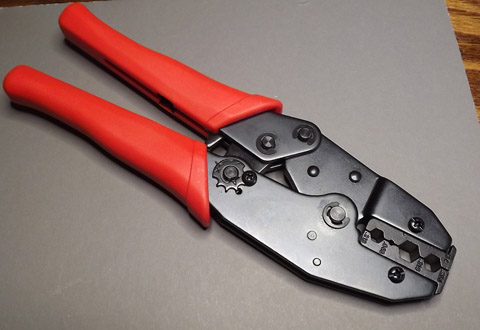
drilling. A gen-u-wide terminal crimper (vs. the $5 auto
shop special) gave me reliable electrical connections. A
band saw, purchased JUST because of some thick stuff aluminum I
had to cut, ended up being used on thinner and thinner material,
on wood, on plastic, on foam, even on cardboard.
Now, my attitude has switched 100%.
"There's a custom tool for that? Here's my Mastercard!"
The latest has been in the realm of attaching
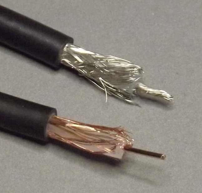
BNC connectors to coaxial cable. In the bad ol' days, I
would do the fancy multi-step stripping of the ends by eye with my
trusty pocket knife, buy solder-on type connectors that needed
fiddly soldering, and messy screw-on clamps that left shreds of
braid everywhere.
About a year ago, when I decided to redo the electrical system on my airplane. The transponder moved about eighteen inches, and that left its antenna cable too short. In the past, I'd been REAL lazy. The local electronics parts emporium sold completed RG-58 cables for a fairly low cost. The transponder and my comm radio both used this off-the-shelf cables.
But the shop no longer sold pre-built cables. I'd have to
build my own. Imagine my joy in discovering that $60 worth
of custom tools solves all that?
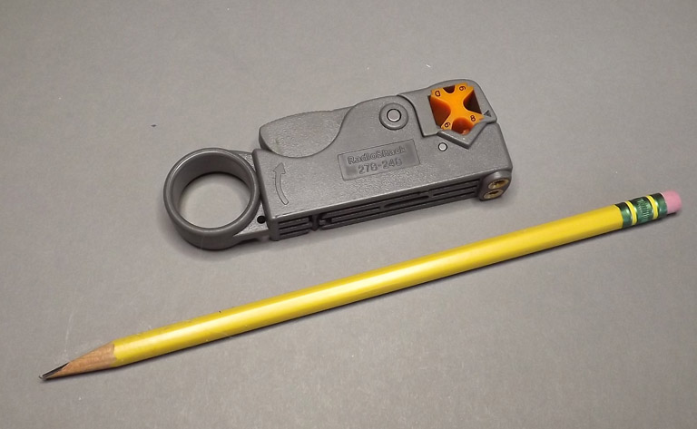
 Something
to be aware of is that these strippers are designed to work with
a variety of cable, so there are some adjustments to make.
You can see the little "X" dial turned to "8" for RG-58
cable. In addition, the internal cutters will have to be
manually positioned to cut the right dimensions. More on
that later.
Something
to be aware of is that these strippers are designed to work with
a variety of cable, so there are some adjustments to make.
You can see the little "X" dial turned to "8" for RG-58
cable. In addition, the internal cutters will have to be
manually positioned to cut the right dimensions. More on
that later.OK, let's go through the process of installing the
connectors.
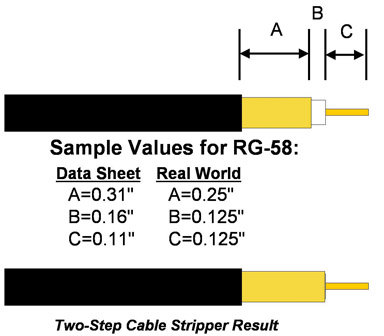 Stripping the Cable
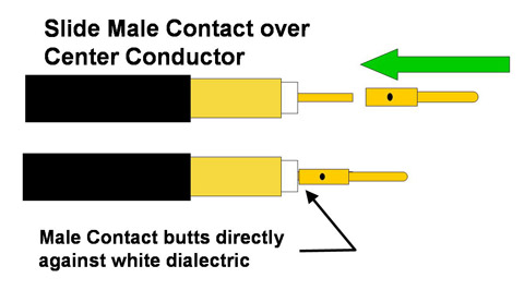 Installing the Center Pin
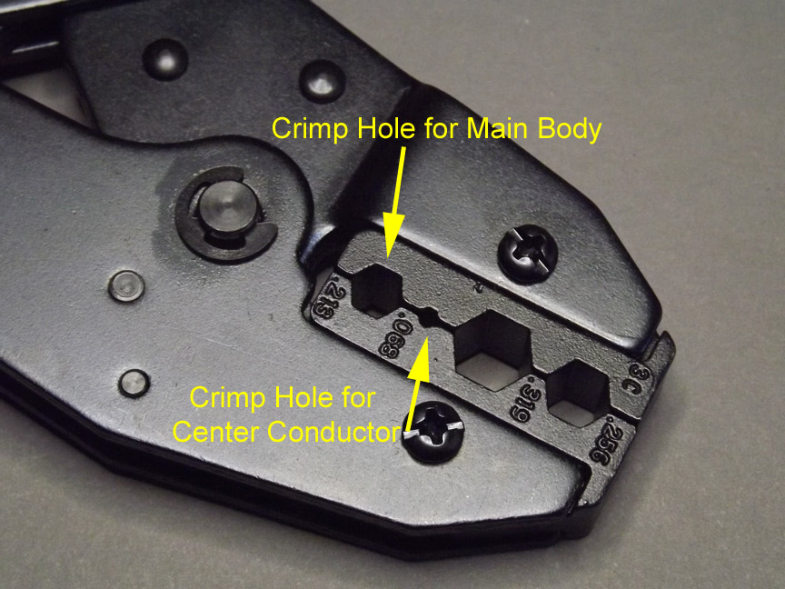
 Add the Sleeve and the Body
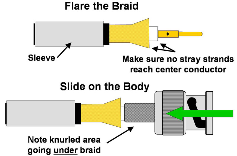
The sleeve is a metal tube that came with the connector.
Slide it over the end, and slide it down out of the way on the
cable.
Open the end of the braid a bit, and make sure there aren't any
stray strands going towards the tip that might make contact with
the center conductor.
Then, slide the main body of the connector over the center
dielectric, UNDER the braid. The end of the body is a
knurled tube which is the part that goes under the braid.
Again, make sure you don't have any stray strands going under the
knurled section.
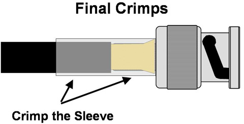 Slide the sleeve back up towards
the end and over the braid. Note the phantom view to the
right... the braid is between the sleeve and the knurled section
of the connector. Using the 0.213" hole on your crimp tool,
crimp the sleeve down against the cable and connector. It's
important that it's crimped against both the open braid section
(for the electrical connection) and the bit of the outer protector
(for the mechanical connection. I crimp close to the head of
the connector, then do another (if necessary) at the opposite end.
Slide the sleeve back up towards
the end and over the braid. Note the phantom view to the
right... the braid is between the sleeve and the knurled section
of the connector. Using the 0.213" hole on your crimp tool,
crimp the sleeve down against the cable and connector. It's
important that it's crimped against both the open braid section
(for the electrical connection) and the bit of the outer protector
(for the mechanical connection. I crimp close to the head of
the connector, then do another (if necessary) at the opposite end.
Last step, when both ends are on: Use a ohmmeter to ensure
that the electrical connections are proper. Make sure the
center pins aren't shorted to the shell, and that both ends are
electrically connected.
