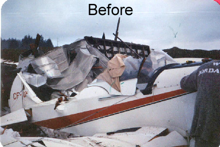
Drew Fidoe rebuilt his elderly Fly Baby after a hangar fell on
it. Durign the process, he'd post his progress to the Fly Baby mailing
list. These reports have plenty of good information for those who
are restoring, maintaining, or building a Fly Baby.
If you're looking for specific information, use your browser's "find" function.
 Glue: My
35 year old FB was constructed using resorcinol glue. This glue has
held up perfectly anywhere where it was obviously clamped. Glue bond
areas where the only clamping pressure was with the nails, as with the
fuselage sides were surprisingly inconsistent, which may be due to age.
All repairs have been with epoxy glues.
Glue: My
35 year old FB was constructed using resorcinol glue. This glue has
held up perfectly anywhere where it was obviously clamped. Glue bond
areas where the only clamping pressure was with the nails, as with the
fuselage sides were surprisingly inconsistent, which may be due to age.
All repairs have been with epoxy glues.
Joystick (figure 6-3 in the plans): The torque tube hole through which the control column pivot bolt passes through at the bottom of the stick has worn so there is an annoying bit of "wiggle" in the aileron. Tom has this play, too, and he reports that it has had wiggle from day one in his FB. It appears that the bushing tubing pieces, consisting of 5/16 I.D. steel tubing welded in place at the bottom of the control stick and the torque tube hole distorted slightly when welded in place. Perhaps welding in undersize tubing and reaming this to size with a spiral hand reamer would eliminate this wiggle, or maybe installing over size tubing to accept oilite brass bushings?
Aileron link (Figure 6-4) I recommend a slightly larger bolt in the aileron link, which connects this to the 3/16 rod end bearing for the aileron pushrods. Mine were bent at the bolt when I bought my airplane, presumably from pilots stepping on the aileron link when wiggling into and out of the airplane since there is no floor boards fitted over this area in (my FB). Later I actually bent one of these linkages in flight in this same spot when I had an aileron gap seal come partially unstuck, requiring full aileron to stay level (the tape goes UNDER the aileron, not on top!!!). The aileron linkages which I have for my second FB project has an AN5 bolt rather than the plans AN4 bolt. If these larger rod end/Aileron linkages can be adapted to this airframe I'm gonna use them.
Flying wires: I am replacing all of my flying/landing wires. Some of these were original equipment, 35 years and 1100+ flying hours, others were half the age with only a couple of hundred hours. I gave Ron a couple of samples for testing to find out if age affects the strength of the wire. Visually, they still looked ok, but some of the original AN100 cable thimbles in the cable eyes were pretty badly corroded. I am not sure if they were a non aviation replacement or what. I plan on upgrading my forward flying wires to 5/16" cable.
Wing to fuselage attachments: My FB has "Diamond reinforcement plates" on both foreward (Station 3) and after (Stn 5) wing spar attach points. This was added prior to the Bowers AD for this mod to station 5. On close inspection, these and the wood structure have held up perfectly, so I don't plan to retrofit the station 5 strap due to the additional work modify my existing structure to accept the mod.
Gas Tank: I have a humungous 18 gallon fuel tank. With the small A-65 fitted to my ship this is overkill for Sunday flying ( the builders of my FB flew it from Vancouver, BC to Oshkosh and back twice, so this feature may have been intentional). This is a lot of weight in extra fuel to lug around if you keep the tank full to avoid condensation. My tank is fitted with a plastic sight tube plumbed from the bottom to the top of the tank. It works ok, but even more plumbing is required to properly vent the tank, and isolation valves on the sight tube add weight. A simple "Cub" type float wire in the cap would be far simpler, and the late Tony Bingelis shows this in conjunction with a tank vent in one of his excellent books. I think that a 12 gallon 'Cub' tank would be better suited for an A-65 powered model.
 Landing
Gear: My FB was fitted with a non-standard landing gear, made of
streamlined steel tubing instead of wood. This gear has held up great
and survived great, but I have no way of inspecting the interior of the
tubes. It has sure survived the test of time, though. My steel
landing gear connects to the fuselage via seaplane float fittings shown
in figure 2-7 instead of the standard landing gear fittings. My axle
tube is 1/8" wall thickness rather than the lighter (.090?) stuff like
on Toms FB. I have never deformed the axle, like some other FB's
have through regular use. I would like to credit this to my superior
flying skills (ha!) but seriously I think its actually due to the heavier
wall axle tubing. For redundancy my flying wire anchor plates
in the axle tube are connected port to stbd by two galvanized cables nicopressed
to the inboard end of the anchor plates, which are slightly longer than
standard to accommodate to holes for the these two cables.
Landing
Gear: My FB was fitted with a non-standard landing gear, made of
streamlined steel tubing instead of wood. This gear has held up great
and survived great, but I have no way of inspecting the interior of the
tubes. It has sure survived the test of time, though. My steel
landing gear connects to the fuselage via seaplane float fittings shown
in figure 2-7 instead of the standard landing gear fittings. My axle
tube is 1/8" wall thickness rather than the lighter (.090?) stuff like
on Toms FB. I have never deformed the axle, like some other FB's
have through regular use. I would like to credit this to my superior
flying skills (ha!) but seriously I think its actually due to the heavier
wall axle tubing. For redundancy my flying wire anchor plates
in the axle tube are connected port to stbd by two galvanized cables nicopressed
to the inboard end of the anchor plates, which are slightly longer than
standard to accommodate to holes for the these two cables.
My gear is slightly taller than the standard wood gear. I prefer this, at the penalty of over the nose visibility in the 3-point, as my airplane appears to be far less likely to bounce when landing 3 point as compared to Toms' FB equipped with standard gear. I think that a good tailwheel makes a big difference, too. Compared to Toms' set-up, the vertical pivot of my tailwheel was set slightly offset foreward from the vertical. I believe that this causes the weight of the tail to automatically straighten out the tailwheel when in motion, creating some directional stability. My FB was fitted with small 6:00-6 tyres with no problems, but I plan on changing to larger diameter tires. 12 psi worked perfectly for the 6:00-6. They were used because my plane was fitted with wheel pants, which I removed. I have a line on some good used 8:00-6's now :)
Weather proofing-metal: My plane was built with all smaller metal
fittings cadmium plated. All of these fittings held up great.
My FB was tied down outside for a few years of its 'life', and was flown
of salt-water beaches. If you can afford it, cad plate at least your elevator/rudder
hinges, and the rudderpost bracket at station 11. Try to fit the hinges
to the airframe permanently the first try, as I found that they never seem
to want to align properly once you remove them for plating/painting/powder
coating. This will save a lot of work and frustration having to identify/tag
the individual hinges to fit their correct position later...unless they're
all perfectly identical (ha ha). My airplane had a compound behind
the hinges to prevent water from getting between the hinge back and the
wood structure, which worked well. Most bolts in my airframe appear
to be surplus. They held up fine with the exception of some which
managed to get some damp along the bolt shank. Tom Staples varnishes/revarnishes
every bolt shank and hole prior to installation of any hardware.
He has never had a problem from this practice so I follow this practice,
too. All interior metal fittings in my FB were 'red lead" primed
and painted and held up great. For painted components, there appears
to be no free lunch. Items that I repainted without the recommended
primer for the paint that I used during my last refit didn't hold up too
well.
Ensure that the paint (and varnish!!!) that you select is compatible
with your chosen fabric coverings' chemicals!
Fabric: My FB had the original 35 year old fabric on it prior to being damaged. It was Ceconite style polyester fabric, with dope through silver and enamel topcoats. The enamel held up surprisingly well, but was ring wormed. Seaplane drain grommets were fitted generously through out the airframe, which I believe helped keep the airframe dry and in good shape. There was no rib stitching in the wings or tail. Industrial grade contact cement was used instead. This glue had deteriorated to the point that the fabric was easily peeled off from the wing ribs :(
Weather proofing-wood: My airframe was well varnished and has very little water damage. I found some blackening around the oak tailwheel support at station 8. The wood was fine after sanding and refinishing, but the tailwheel spring bolt was toast. I would give extra attention in this area. My plywood structure from station 9 aft was fine due to good varnishing and plenty of drain holes. I think that a good varnishing job is especially important back here as lots of crud seems to accumulate in this area. Mud Daubers appeared to have liked these holes, too.
Plans conformity: I believe that my FB was built to the original EAA article drawings on building the Fly Baby. There are some revisions and dimensional differences between the EAA articles and the plans. If you are working with an older airframe and replacing/repairing components, ensure that the parts that you make will fit your airplane! Remember that many components are 'make to fit", so purchasing components premade (such as from an abandoned project, for example) may not fit your project without modification. I have found this one out the hard way!
Happy building/restoring,
Drew
I have a few more points from working on my Fly Baby. And now for another edition of "This Old "Plane"!
 I found a few
resorcinol glue joint failures in my elevators (figure 3-7) and rudder
(figure 3-4) where the forward end of their ribs join the box spar.
The glue contact area at the forward end if these ribs is quite small.
All other 35 year old glue joints in all of my tail feathers were fine.
I added doubler reinforcements, as shown in the figure 4-20 nose ribs,
to both the elevator and rudder ribs at the box spar ends using epoxy glue.
I considered using 1/16" gusset plates like those used in the Pietenpol,
but considered this an easier fix. I like epoxy, as it doesn't require
great clamping pressure to make a good strong joint. Especially handy
in restrictive access areas hard to clamp or nail.
I found a few
resorcinol glue joint failures in my elevators (figure 3-7) and rudder
(figure 3-4) where the forward end of their ribs join the box spar.
The glue contact area at the forward end if these ribs is quite small.
All other 35 year old glue joints in all of my tail feathers were fine.
I added doubler reinforcements, as shown in the figure 4-20 nose ribs,
to both the elevator and rudder ribs at the box spar ends using epoxy glue.
I considered using 1/16" gusset plates like those used in the Pietenpol,
but considered this an easier fix. I like epoxy, as it doesn't require
great clamping pressure to make a good strong joint. Especially handy
in restrictive access areas hard to clamp or nail.
My horizontal stabilizer landing wire support bracket (the one which sits astride of the top rib in the vertical fin, fig 3-1 and 3-5) was in good condition. However, one of my previous maintenance squawks was that their angled 'tangs' were a little bit short, so there was little room to fit and safety the turnbuckle clevis pins due to clearance with the side of the fin. I made a new one with 1/4" longer 'tangs' than illustrated in Fig 3-5. Of interest, instead of the triangular wood reinforcement block fitted to the bottom side of the Vert Fin rib from this bracket shown in Fig 3- of the plans, my 'plane is fitted with a robust laminated square wood block (don't ask me why).
My friend, Tom, modified where his lower horizontal stabilizer flying wires attach to the lower fuselage. Instead of drilling a 3/16" hole through the tail post underfin (page 3-15 para 3) he attached his wires directly to the tailwheel spring support bracket bolted to the bottom of the fin (Fig 2-6). He can't remember exactly why he did this, but his wires are attached to this bracket by the same vertical 3/16" vertical bolts that hold the tailwheel spring in place. I was kind of wary of this installation, but it has held up fine. (NOTE Bill Rotenberrys note at bottom) Perhaps if a builder wanted to avoid the plans method of drilling across the lower tailpost box spar (I've done one, it has to be done with care), lower wire attachment hardpoints could be welded directly to the tailwheel spring support bracket.
Prior to bolting the tailwheel bracket to the tailpost for the final time, decide if you want the 3/16" vertical tailwheel spring attach bolts head side up or the nut side up (I've seen both.) I would recommend the non-aviation practice of head side down, because once the bracket is attached it's a pain to remove just to replace two bolts.
For temporarily fastening and aligning metal fittings on wood (prior to using to fitting as a drill guide for the wood structures an example), use double sided tape under the fitting to prevent it from moving on you. This is especially handy when aligning the horizontal stab incidence (Fig 3-9) for aligning and immobilizing the forward attach bracket prior to drilling the bracket to fuselage bolt holes.
:) Cheers,
Drew
My FB is fitted with a Maule model SFSA tailwheel with 6.5" dia solid rubber tyre. I think that this, or the model 2000 Scott unit, are perfect for this plane. They have solid tyres, parts are readily available and they have a full swivel capability. These both weigh about 6lbs. Tom has a fairly narrow, 4" diameter tailwheel on his FB, and I feel that it's a bit marginal on rough grass fields. I would get a tailwheel with full swivel capability, as it helps when you want to make a tight turn while taxiing, or when pushing the airplane backwards into the hanger. Tom doesn't have this feature on his, he has to disconnect the tail wheel springs to push the plane backwards, also his ground turning radius is wider compared to mine.
If you buy a used tailwheel, ensure that the full swivel unlocking cam (which disconnects the 'steerable' feature) is in good condition. This cam can disconnect by accident at inappropriate times if it's worn or incorrectly set up. The cam shouldn't disconnect until you give full rudder (I think that mine only disconnected from steering to full swivel with full left rudder). I have rebuilt four of them myself using parts from Aircraft Spruce, bought the sealed bearings from the local industrial supply house (dishwasher...right?) and I have machined my own replacement bushings. If the wheel has a shimmy damper, they're spring loaded if I remember correctly. You really get what you pay for in a tailwheel. I prefer larger tailwheels for rough ground, but the simpler, cheaper homebuilder specials would work fine for someone who has reasonable manoeuvring room, and may not want the potential liability of the full swivel feature. Just make sure that if it is a homebuilder special that it will take the weight and abuse of a FB.
I use compression type tailwheel connector springs AC Spruce P/N 06-15600. They're also called 'safety springs'. I had a situation once when landing a friends 'Chief' fitted with 'bed spring' style tension springs that were always had tension on the steering horn. I had just touched down 3-point when the port side spring abandoned the aircraft, the stbd spring's tension pulled the tailwheel to stbd and I groundlooped the plane. The port spring popped off and just as my friend was complimenting my superior flying skills :( go figure, he spoke too soon. We found the missing spring at our touch down point. No damage but it was embarrassing! I replaced those springs with compression ones the next morning. When I fit compression style springs I ensure that there is just a bit of slack in the spring connection to the steering horn, when the wheel was is farthest from the horn, (on my plane when the tail spring leaf is in its 'relaxed' position). This eliminates the loading on the steering horn and rudder assembly. My steering horn was cracked in the same positions as on Ron's web site.
Some more personal opinions on FB ground handling. The straight axle landing gear, while a bit narrow, makes for good handling because the geometry of the axles is always the same. I don't think that the narrow track is an issue as the FB is light compared to certified ships. I have flown two different Rag 'N Tube planes whose alignment was out of wack, making directional control interesting. My FB was a real pussycat compared to them. I had problems with smooth, bounce free landings at first, until one experienced FB flyer had me reduce my tyre pressure from 20 to 12 psi (600-6 Tyres). What a difference.
The late Tony Bingelis has an excellent article on tailwheels in "Sportplane Construction Techniques" (the yellow one).
Cheers,
Drew
 Hello all,
WINGS N THINGS
PLANS VARIATIONS: Be aware that many early Fly Babys were built from the original EAA articles, and the follow-on reprint in the EAA publication "Building the Wooden Airplane". There are variations from the current plans including slight differences in spar spacings due to the lack of the full size rib layout of the plans. Also, builders do occasionally make minor measuring boo boos and work around them :) If you must rebuild or fabricate new parts for an existing airframe (or you are taking over an abandoned project) measure all of your existing components carefully and make the new components to fit the ones that you already have to save annoyances later.
Wings are hard to inspect, especially if you have never opened up those inspection rings!
Be aware of hidden surprises, especially if you didn't build them yourself. Keep on the lookout for mis-drilled holes, non standard drag/antidrag wires, and other sins.
Always keep an eye open for stains indication water ingress and possible deterioration. Look for rust, evidence of varmints and loose fasteners.
AILERONS, CONTROLS & METAL COMPONENTS
Swing link alignment: ensure that the "swing link" for the "long
aileron push rod" is correctly shimmed so that the push rod lines up correctly
with the (fig 6-4) "aileron link". The long aileron pushrod fits
through the hole in the fuselage side just aft of Stn 3, and must clear
the stn 3 bulkhead. Both sets of my wings have shim blocks (one is
1/2" the other 3/4) under the swing link which are not illustrated in the
plans. Also ensure that the "long aileron pushrod" has adequate clearance
through all of the ribs. This can sag a bit, so make sure that nothing
rubs through the full travel of the rod with the wing in the upright position.
This can remove paint from the rod leading to wear and corrosion.
Fig 4-5 shows the swing link and 4-29 shows the installation without a
shim block.
Aileron Link: (Fig 6-4) I strongly believe that the weenie
little 1/4" AN-4 bolt welded into the tube for the female AN 951 Rod bearing
is undersized for the job that it does. These are easy to bend if
you don't have floor boards over them and I bent one in flight when an
aileron gap seal let go causing a very wing heavy condition (the tape goes
under the hinges not over top!). I upgraded mine to 3/8" male thread
rod bearings, with AN-6 threaded bushing riveted into aileron link tube.
This keeps snow-ball mods to a minimum as I couldn't find a 3/8 female
rod bearings to fit the stick. I found these fittings for cheap at
the fly-mart brand new...they came mounted complete with some other fittings
attached to some sort of jig assembly for $5 each.
WOBBLY STICK?
(Fig 6-3): If the control stick moves appreciably (in aileron
control) without rotating, the torque-tube assy bolt, which attaches the
stick to the torque tube, may be worn (it allows the stick to pivot in
pitch on the torquetube), or the holes/bushings in the stick/torquetube
may be worn. This can be a bit annoying in flight as this gives a
bit of slop in the ailerons. Maybe oilite bushings would help?
AILERON HINGES:
I had a hard time tracking down 1" structural hinge material.
I finally found it at Demel Aircraft in Penticton. Here's a scary
one. The ailerons on wings "Y" only had 3 hinges installed, with
hardware store variety aluminum "wrap around" cowl hinge. The holes
for the screws were oversize, mis-drilled, and cheap non AN screws
were used for attachment. Yikes. Enough said.
COMPRESSION STRUTS/RIBS (FIG 4-4):
Compression ribs in both sets of my wings have half of the compression
rib-end "tangs" drilled with 3/16" holes (vice the 1/4" holes shown in
the plans) to fit the Drag/Anti-drag cable turnbuckles' 3/16" clevis pins
fitted to these wings vice the 1/4" hole illustrated in the plans. Makes
sense to me. The other holes are drilled for 1/4" holes as per plans
to fit the nicropress sleeves for the other end of the cable. I noticed
that all the compression rib-end "tangs" were all built to the same angle.
Since compression struts/ribs have different spacings along the wing this
can create trouble with side loading on the turnbuckle as the tangs are
at the wrong angles, especially at the wing root. I would ensure
that the "tangs" point directly at their opposite number to ensure that
there is no bending moment on the turnbuckle, otherwise the forks will
get bent. Another point is to plan where the all the Drag/Anti-drag
turn-buckles will go. I would not place turnbuckles under the plywood
covered wing root as the are nearly impossible to access later on.
Put them in the positions illustrated in fig 4-1 and you'll have no problems
:)
( also see "Wing Wire Junction Blocks")
If fasteners are loose find out why, is there rot? Are the fasteners rusty under the wood? Has the wood just shrunk a little due to humidity? Don't cover up a problem and take care not to overtorque bolts in wood structures.
PAINT N VARNISH
External Metal Fittings:
Use the best quality coatings that can be afforded for corrosion protection.
I have one set of early 1960's vintage wings (X) which had the wing spar
to fuselage plates cadmium plated. They are still like new, even
after a few years' external tiedown. I think that cheap spay-bombs are
not the way to go on these, I also have a rusty spray bombed parts from
wings (Y) to prove it.
Internal Metal Fittings:
Once again, use quality coatings. I've found corrosion on poorly
painted metal fittings such as compression struts and aileron push rod.
They appeared to be spray bomb painted with a single coat, and back areas
shadowed from the spray can rusted. If more exotic products cannot
be afforded, a good cleaning (surface preparation) followed by two coats
of hand brushed on "red lead" Tremclad appears to have done the trick on
X. If you are just touching up metal components, ensure that all
the paint that you are using is compatible with the paint already there,
otherwise you'll just make extra work for yourself (guilty!). Also,
if you are recovering, ensure that the paint on the metal components is
compatible with the recovering chemicals which may come in contact with
them. For example, Polyfibre products will melt enamel paint but
not epoxy based products.
Varnish:
Try and decide early which covering system will be used as spar varnish
isn't compatible with products such as Polyfibre. Don't assume that
it will be ok, and don't be tempted into using "polyurethane" varnish with
Polyfibre. Some ultra-liters use this instead of the recommended
epoxy varnish. Polyfibre melts polyurethane varnish, I tried
this out on a small component and made a mess. I think that this
is especially important if you use the Poly-Tack to glue the fabric to
the airframe or ribs as this could create problems later. You can apply
Polyfibre safe epoxy varnish over the others, but if you plan to glue ribs
to the fabric follow the Polyfibre instructions and remove all old varnish
first to be safe (see following).
Neither set of my wings were stitched. The old ones (X) had original '60s vintage experimental Dacron attached with rubber cement. It peels off the ribs very easily, which I think is more a factor of age than the glue. My second set, Y, had the fabric simply doped to the ribs. I can pull the fabric away from the ribs on these. Since the fabric punches fine on this set I looked into alternate attach methods, but will stitch these. Thank-you to all who got me off my hair brained idea of using staples instead of rib stitching :)
I've found a lot of varnish deficient areas, in wings (Y). Prior to closing up a section with fabric or plywood, ensure that the section is adequately protected. I personally believe at least two coats are a good idea, and an extra coat or two can't hurt under metal components and areas where water could potentially collect. I've tried epoxy varnish, spar, polyurethane and varnishes. I like the epoxy varnish best but spar varnish is more convenient.
By the way, a chemist homebuilder friend told me that hardware store Polyurethane varnishes aren't a true polyurethane. They add a small quantity of polyurethane to regular varnish and then the catalyst too. The chain reaction for the polyurethane setting up is delayed by other chemicals in the varnish, but do set up within a few months of manufacture while still in the can, negating any polyurethane benefit. If you are going to use polyurethane varnish you may want to purchase it from a high turnover store? For box sections someone on the list suggested painting the entire structure with a thin epoxy. I think that West System was mentioned. This sounds good to me, it would minimize time waiting for varnish to dry and minimize the potential for missed areas to varnish contamination of glue joints.
WING WIRE JUNCTION BLOCKS (Fig 4-2) and WING WIRES
Carefully inspect the Figure 4-2 Wing Wire Support Pad junction
for rot and delamination of the (fig 4-2) hardwood support blocks from
the spar. Water can get in here, and glue ages. Look at the
Fig 8-3 plywood spacer under the fig 8-2 "Wing Wire Anchors" to see if
there is warpage or popped nails (the warpage may have been caused by over
torquing wing wire anchor bolts too but there should be no delamination
of this plywood spacer).
Remove the inspection plate covers under the Fig 4-2 Wing Wire Support Pad junctions (do you have inspection rings here?) and have a careful look at the hardwood blocks. Viewing of the front block on the front spar may be obstructed by the leading edge aluminum. Look carefully at the block for splits, cracks, warpage or stains.
Shine a strong light at the glue line between the block and the spar. Does the glue line appear fractured? Try and slip a .002" feeler gauge between the block and the spar. If the feeler gauge slips in between them the support block may have delaminated from the spar.
My older wings (X) blocks were delaminated and I was flying them this way unawares. The two compression strut bolts were the only thing keeping the blocks from shifting on the spar. It is very difficult to detect if you aren't looking for this, they may look great otherwise. These were glued in 1965 with aerolite glue, I believe that this may be an age issue for older airframes. Also, there may a difference in expansion between the dissimilar woods?
If the blocks look OK but the plywood cap is badly warped or stained I recommend removing them and having a peek underneath. Look at the block to spar intersection after removing the plates to look for rot or delamination.
After removing the old glue I reassembled mine with new plywood plates using epoxy with plastic minifibres, using hardware store bolts to prevent glue from entering the screw holes. I used a 1/8 plates vice the Figure 8-3) 1/4" plates and added 5 layers of fibreglass cloth between the plywood plate and the top the 4-2 Support Pad Junction. The glass cloth wraps around the side of the blocks as much as practical with the compression rib and bolts in the area. This was recommended to me by a local homebuilder/Engineer friend. This has the benefits of an additional moisture barrier to the junction, cleaning up imperfect holes at the exit of the hardwood block holes minimizing unnecessary loads on the Wing Wire Support Pad through bolts, and adds shear strength to the hardwood block/spar junction. When I did this I ensured that everything line up with the WW support pads.
Figure 4-2 Wing Wire Support Pad junction Bushings/larger bolts: The plans make vague reference to respecting the edge margins illustrated in the plans when drilling the hardwood support blocks for the fig 8-2 "Wing Wire Anchor" 3/16" bolts. If you are drilling for bushings or 1/4" bolts shouldn't these blocks be a bit thicker? (if this was done compression rib c-2 would have to be shortened too) With this in mind, my wings (X) with 1/4" wing wire bolts have extra material added to the Fig 8-2 "Wing Wire Anchor Plates" to respect the plan's edge margins illustrated for the 3/16" bolts. My wing (Y) plates did not take edge margins into account and I'm replacing them. The edge margin is just a thought, I don't believe that there has ever been a problem from this but it could be an issue for heavier gross weights.
LEADING EDGES:
My wing (X) have beautiful 3/32" plywood leading edges instead of HH
aluminum flashing. They are super strong and make the whole leading
edges a D section. This isn't a recommended mod (I would think this
would be a change to the basic structure) but the original builder did
this for aerobatics. I really like it because you can push on it
without denting it when maneuvering into a tight hanger spot. I get
afraid when I go upside down myself
INSPECTION PORTS and PLATES:
Put all those inspection plates and ports illustrated in the
plans. These are around the plywood covered wing root (Fig 4-29).
Ensure that they are positioned so you can actually get tools to access
all those components inside. You wont regret it if you ever have
to get in there again, plus you wont have to remove the wings to inspect
control system integrity at annual inspection.
INSPECTION RING PLACEMENT:
Same as above with fabric inspection rings. I would ensure that
they are placed under all turn-buckles, control system intersections/connections
and Figure 4-2 Wing Wire Support Pad junctions.
WATER: ensure that you protect against water. Ensure drain holes are at the farthest point aft as possible to the trailing edges. In particular, ensure that there are drain holes drilled in the plywood reinforced area forward of the aileron sub spar (Fig 4-23), and in the ply covered wing root area in the front of each spar and the trailing edge. A good varnish job is very important here. too. Being a professional sailor I like varnish and lots of in "high risk areas". I like seaplane grommets because they supposedly draw away moisture in flight. Other people prefer standard ones aesthetic reasons, and you can see if cooties are blocking the drain easier.
WING WIRES:
Follow the plans and install Stainless Steel 1X19 wire for all wires.
Multi strand 7X19 wires can supposedly stretch a bit more than 1X19,
and if moisture or mice get in the wings galvanized wires wont hold up
like Stainless Steel ones. I have both, the mid '60's stainless wires
look like new, the late '70's galvanized required replacement, and have
been upgraded to the 1X19 SS. Use only Stainless steel AN100 cable
thimbles in the nicropressed cable eyes. Coated steel cable eyes
rust and cheapies bend under load. I've found these conditions in
various wires of my wings and airframe.
I'm planning on upgrading to 5/32" wires for my forward lower pair
of flying wires on each side. I'm not sure if this upgrade will require
larger holes in the Fig 8-2 Wing Wire Anchor plates. The clevis pin
is larger than my original 3/16 clevis pins of my original turnbuckles.
I'll replace them if the edge margin isn't to plans.
On the subject of Fig 8-2 wing wire anchor plates, one lower set was bent too shallow of an angle, causing a bending load on the plate and turnbuckle. The plate should be such an angle that the turnbuckle end of the plate should angle directly at the axle. Same thing for the Fig 8-1 Landing wire terminal. If the turnbuckle end doesn't point directly at the top side wing wire anchor plate the turnbuckles could get bent, I got a set in this condition from a scrapped FB.
WING WIRE BOLTS: If you look over the various catalogues you'll notice that up to about AN4-50 the bolts are fairly cheap. After this they triple in price. My rear wing spar wing wire anchor plates on one set of wings are the cheap AN-50s and they fit, but it does dish the fabric slightly as the plate sits a little low. This may save some $$$ for budget builders. I'm building a shallow fabric support tray (ensuring drainage) to support the surrounding fabric here without distorting the airfoil shape, and am going to fit a simple sheet-metal fairing over the wire anchors.
My forward plates are slightly lower than standard as well dishing the fabric, (but the full thread is used for both front and rear spar anchor plates without recutting new threads on the bolt ends). I'm going to try the same treatment on these, build them in a box to support the surrounding fabric in the proper airfoil position and cover the wing wire anchor with a sheet metal fairing. Maybe this will lower the drag at the wire to wing intersection, who knows.
My other set of wings (X) have re-threaded AN-4 bolts and are 1960's vintage original. The threads were bearing on the wing wire anchor plates, which isn't good practice, but they were aerobatted this way and lasted 1100 plus flying hours with visible distress but NDT is the only real way to know if they were safe...better off to replace them. I know that rethreading the bolt threads is common but it does bother me as aviation threads are rolled, not cut. If you must recut the threads on your bolts, I would go with the AN-4 size and have someone experienced do the job for you. (I know a bit about threads, I'm currently employed as a machine shop instructor) These wing(X) wire anchor plates follow the slope and height of the fabric's aerofoil shape perfectly, and custom angled washers were brazed to the upper wing wire anchor plates so that the bolt heads have full contact. Two variations to think about!
VARMITS:
I found a mouse nest in one wing and WHAT A MESS it was! I had
to replace one compression strut, all internal wires, and clean and repaint
most metal components. The urine is very corrosive to all steel components
as well as the aluminum leading edges. The little poops work themselves
everywhere, including under the fabric. As suggest by list members
I wore mask, gloves and coveralls to clean out the mess and scrubbed everything
with a disinfectant detergent. Mice get an Ebola-like virus called Hanta-virus.
Bad stuff.
I think that's everything of note so far. Like I said at the start
the opinions here are my own, but may help with people building, restoring
or perhaps someone making a pre-purchase inspection. If I'm off track
anywhere please let me know, I don't want anyone to encounter the problems
that I've had to deal with (but don't want to lead anyone astray either!).
It's certainly been an education to date...
Cheers,
Drew
Extra inspection notes:
Always check compression strut C-2 spar-bolts
.they are usually corroded
form water at the wing wire pads;
Check for loose spar pad blocks;
Also note the following below:
I've experimented with a fancy tensiometer that I purchased at the Arlington fly-in this year. This is a very compact unit, which fits inside my inspection holes and is very easy to use when adjusting wing drag/anti drag wires with the fabric in place. Following the instructions (Page 4-14 para 10) setting the turn-buckles hand tight plus one complete turn I found that I could easily get the wires within 25 lbs of each other, I then fine tuned the turnbuckle to even out the tension between each drag/antidrag wire pair in the "X". The hand tight plus one complete turn method gave me a higher preload on my wing root end wires than the two outboard sets, I guess the shorter wires have less stretch? Another interesting note was adjusting on wire of the cross pair will affect its opposite by up to 15 lbs, something to keep in mind when making large adjustments or when trammelling the wing for the first time.
From my experience working with two different pairs of wings, constructed by different builders, for those currently building/restoring I would suggest the following:
A simple way is to just fit the bolt in place, and fill the surrounding oversized hole with epoxy and tighten everything up. You can just goop in the epoxy and bolt it up wiping away the excess but I did it a little differently on my hinge screw holes. I used "Cold Cure" epoxy, a thin 24 hour epoxy by Industrial Formulations sold by Industrial Plastics and Paints. When I replaced my hinges I drilled a 5/32" sprue hole to intersect the centre of the oversized/worn bolt hole (drill at an angle from above so the glue may flow down hill, also allowing the air bubbles to escape).
I cleaned out the sawdust and assembled the new hinges with new screws with a coating of cold cure on the screw and in the hole and aligned everything up. I then injected the Cold Cure into the 5/32" sprue hole with a fine tipped epoxy syringe. The Cold Cure epoxy flows fairly easily, and encapsulates the screw/bolt, which is why the intersecting 5/32" hole should be started from above the oversized bolt hole if possible, this way the air bubbles flow up and out. Don't worry too much about air bubbles, pop the larger ones and inject more epoxy in, if required add some cello tale to keep the glue in the 5/32" sprue hole when your done, but it should ideally run downslope.
The Cold Cure glue pot life lasts for a couple of hours so you have plenty of time to add some more glue as the space around the bolt will soak up a lot of the glue as it settles in the empty space. I had to do this procedure twice, as the first gluing settled out pretty well and I didn't hang around to add more glue so by the time it cured the 5/32 sprue hole was empty, the second batch filled it all up permanently. If you want to easily remove screws later you may want to still insert a metal bushing but bolts break free from the epoxy fairly easily, especially with a bit of wax on them.
To save the syringe for next time drain out the majority of glue, let it cure and peel out the leftovers.
This method may not be for everyone, but it is permanent and self jigging saving on work :)
A good note from From: Bill Rotenberry:
Thanks for your experience and insight regarding the tailpost and tailspring bracket. The timing of this discussion was near perfect in that I was about to build the lower box section. I have incorporated most of the suggestions regarding the tailspring issue - upgraded from AN-3 to AN-4 bolts; three bolts versus two; steel bushings on every hole; and I've added 1/8" ply to the front of the lower tailpost for extra rigidity. The only thing I didn't do is use hardwood instead of spruce as the insert piece. To paraphrase a section from the manual, if this tailspring bracket comes loose I'll need a whole new airplane.I also found it interesting that the old Fly Baby Bulletin (Ron sells copies) discussed this topic 36 years ago. In the Sept. 1967 copy it notes ". . . consider adding steel tube bushings thru the rudderpost". This is a ". . . possible weak spot in the plane construction and some play might develop without bushings there". At the 1967 Rockford Fly-in a Fly Baby owner noted that some play had developed in the tailspring fitting. And in 1967, this plane could only be a few years old!
In the Nov 1967 copy it notes ". . . use a hardwood filler on the fin post. This will help the tailspring from working loose".
And Drew, your issue regarding the stab wire brace fittings was also a concern in 1967. Drilling an accurate hole through the thin tailpost is difficult. In the Dec 1967 copy of the Fly Baby Bulletin it speaks to these fittings and the bolt through the tailpost. In that Bulletin is a drawing of a new tailspring bracket that includes brace wire fittings, thereby eliminating the need to drill a hole through the width of the tailpost. It appears simple and effective, although may be a bit tricky as a retrofit. The drawing also notes adding a piece of 1/8" ply to the front side of the lower tailpost.
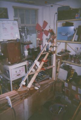
 A quick update
on my progress.
A quick update
on my progress.
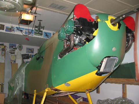
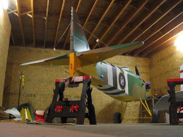
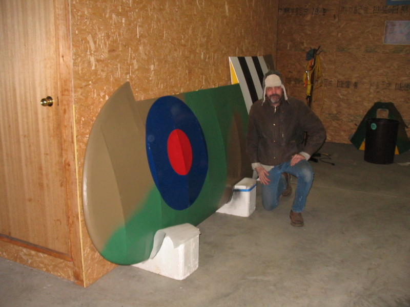
Since arriving home from my navy overseas deployment I've managed to get a fair bit of time in my shop working on my Fly Baby. It has been sitting patiently waiting for me to get home, the fuselage turtle-deck and fin still requiring fabric, and some minor taping left on the control surfaces prior to build-up coats. The zero-time A-65/75 was hung on the firewall awaiting accessories, eyebrows and nosebowl construction.
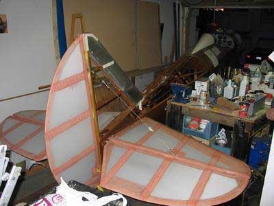
I attached the remaining fabric and tapes to the fuselage, all were attached utilizing the Stitts/Polyfibre methods and materials (actually, all fabric and tapes on the aeroplane were attached using the mentioned methods and "rules" for overlaps of tapes, etc. This includes stitching all ribs, and using proper epoxy varnish on the structure prior to Polyfibre chemicals!). I applied by brush two seal coats of Polybrush to ensure that the fabric glue is set to the fuselage sides, ironing at 225 degrees between coats.
The fabric job on the fuselage sides is so-so in terms of looks. I covered the fuselage sides while up-right in the landing gear. I had a heckuva time laying the fabric in sections before the chemicals set-up. As a result you could see each section of fabric applied. Next time I would remove the landing gear and lay fabric onto the fuselage horizontally. The fabric could be applied to the sides well in advance of the rest of the fuselage covering, then the landing gear brackets could be bolted on for a nice, professional and clean look. This would make an easier and by far faster way method (as the Polyfibre books recommended) as I had to spend a lot of time working the glue-runs and high spots down with a 225 degree calibrated iron, otherwise the plane looks pretty darn good.
The ribs were stitched and reinforcement patches laid, as well as the
seaplane drain grommets. I was then gonna go straight latex for build-up
but a friend gave me two cans of Polyspray (silver) which he had laying
around from a previous project. I used a 4" foam roller to apply
a coat of Polybrush and decided to call it quits with the chemicals, even
though I have a can and a half left of Polyspray left over. The foam
roller did a great job of the Polyspray, it looked fantastic but I didn't
want the fumes in my house (the garage is under my place and fumes work
their way up regardless of my taping and sealing of doors and electrical
outlets).
 Restoration
Notes: Painting with Latex
Restoration
Notes: Painting with LatexBack when I installed my new, stainless steel firewall on the fuselage I made strategic cut-outs for the tachometer, wiring and sensors. They were all made as sort of access ports instead of simply drillings for each item as I wanted flexibility both now and later. This has proven very convenient in the final refit process, I will simply add stainless steel cover-plates over these ports when complete. One thing that I wish I had done was to pre-drill the cover-plate fastening holes in the firewall as access with the engine in place will be difficult. I can always drill from the rear I suppose...
ENGINE:
I had previously given away my primer to a buddy finishing up his RV-4, so I scavenged a replacement a couple of years ago. I purchased the correct fittings for the primer lines at a local industrial supplier, but found one fitting on the primer was an odd-ball. The 1/8" fitting was too small and the 3/16 too large. Pipe-taper didn't work either. I fiddled about with the bits and fitting that I had on-hand until I got it to seal, testing the integrity of the primer system with methyl-hydrate.
I replaced the copper tubing and fittings for the Scott oil pressure gauge. I couldn't find an orifice fitting for the engine oil pressure exit to the gauge line so I pressed a homebuilt aluminium orifice snubber into the engine oil-pressure outlet fitting.
I am had a bit of a problem finding the correct adapter fitting for my Scott Oil Temperature gauge sensing line. This is the fitting which screws into the oil strainer and seals up the temperature bulb, and according to Ron this was a Cessna part. It looks like I can order it from Aircraft Spruce http://www.aircraftspruce.com/catalog/inpages/oiltempbulb.php After some thought about this, and as my oil strainer isn't in the best condition anyhow, I have decided to go with a home-built oil filter adapter. I machined two prototype adapters designed to accept a remote, firewall mounted oil filter, but have finalized on an idea that I saw in a magazine where the oil filter mounts directly on the rear of the engine, using a filter intended for a Ford V-6 engine. This arrangement has less chances for leaks and is far simpler to construct, I have a couple about 90% complete now, I will post updates on this experiment once I am satisfied with the results. As I'm going to go for the oil filter option and I have to install an electric oil temperature gauge in place of the Scott unit (the Scott temp sensor cannot be used with this new filter arrangement as there is no port for the sensor). The electric unit makes sense as I can locate the electric sensor anywhere. I hoped to locate it in the oil tank drain, but it doesn't look like this will work, so I plan to braze a brass threaded port into the oil tank wall to accept the temp sensor. To make the gauge independent of the electrical system I'm investigating the use of a magneto "tap" designed to power such a device. This little goody came with some surplus timber and hardware which I purchased from a retiring homebuilder, I'm not sure where it came from but it's new in the envelope. If anyone has experience with these I'm all ears.
I have fitted a J-3 style exhaust system in place of my previous straight-stack arrangement in the hope of a quieter cockpit. The exhaust system is a used unit purchased with my A-65 resto project, but I had to find a source for the clamps. As hose clamps are too light duty, and standard exhaust clamps unusable for this application I checked with my local Volkswagen supplier and found two-inch diameter band clamps specifically designed for exhaust systems. These are available on-line from http://www2.cip1.com/ part number VWC-113-255-341-A. These cost a whopping $2 each.
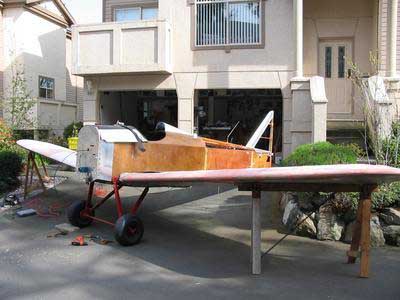
 COWLINGS:
I have converted from a well constructed pressure cowling, with a rather unattractive nosebowl and large spinner to a classic Cub style jugs in the breeze arrangement. I purchased a used, rather tatty fibreglass Cub nosebowl and made the necessary repairs. The aluminium wraps took a lot more time than expected, and although it isn't "perfect" it's airworthy and presentable. As I have mentioned in previous postings, the Fly Baby firewall is a different shape from a Cub, therefore the side-wraps will be completely different between the two, and a Cub exhaust will not allow as clean of a cowling in the area where it enters the aluminium side-wrap sides. Also due to these angles, the lower nosebowl requires minor modification in order to accommodate the different angle of the cowl-wrap to nosebowl intersection. I recommend the .025" aluminium recommended in the plans for the cowl wraps. I used what I had on hand in my shop, .020" is a bit thin and .035, is a bit more difficult to work with as it must be given a permanent set in the angles. I don't recommend the hardware store variety of pop-rivets, I used a couple of cheapies after I ran out of the stainless steel structural rivets which I purchased from a local fastener specialty whole-sale outfit. I also AN470 dome-head universal rivets on the cowling skins, using a hammer to form the shop-head, bucked by a steel plate set on the concrete floor. I made an effort to keep a close and tidy cowling, as many Cub-style homebuilt cowls are rather loose and open-looking for my tastes. This is easier said than done, the take more time to form correctly and making close fitting cowls can lead to chafing if not careful. If I were to do this again, I would use all .025" 6061-T-6 aluminium sheet and leave a bit more of an allowance for cowl movement.
While working around Station 3, I discovered that the most of the AN-6 bolts of the Figure 1-19 landing wire support plate (it supports the master turn buckle in front of the instrument panel) turned fairly easily and some were bottoming out on their threads when attempting to tighten them up, so I removed all for closer inspection. It appears that they were originally tightened correctly, but as the wood structure aged they became loose with time, and the lack of grip length caused the nuts to bottom out on the threads of the bolts when retorqued. I pulled all of the bolts and noted no decay, nor evidence of any abnormal stresses evident in the structure or bolts, but I did find a surprise. Refer 1-6 detail D and Figure 1-9 detail A. The lower AN-6 bolts did not fully penetrate the additional 1" spacer illustrated 1-9 detail A. My 1-19 landing wire support plates appear to be slightly different from the plans (this was an early airframe which I'm certain was constructed using the original EAA articles) but I would recommend that new-construction builders be aware of this area to ensure that adequate support is provided in the Station 3 core to support the bolts.perhaps install a longer block? I considered my situation carefully, and as the area was in good condition (and I know that my 1000+ hour airframe has experienced aerobatics) I simply varnished the holes and bolts, and carefully tightened up the AN-6 bolts up with extra washers to eliminate the original loose bolt/grip length problem.
Overall, the aeroplane is almost ready to leave for the airport now. I have a few more items to finish up and am waiting to a new altimeter. I'm still working on hangerage as my last one didn't work out.
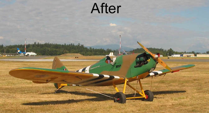
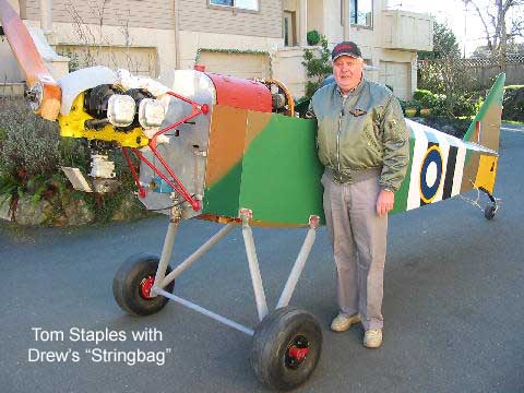
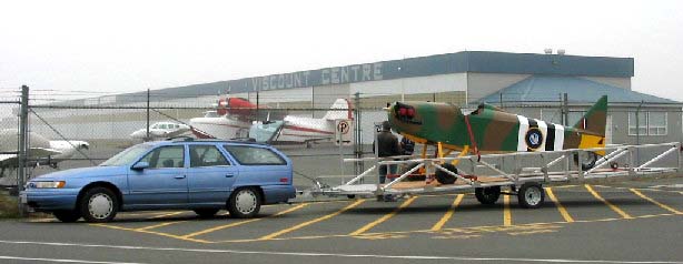
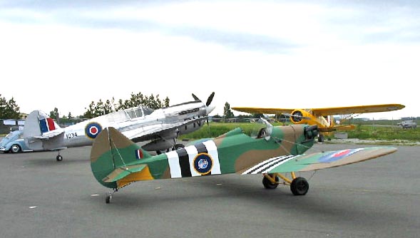
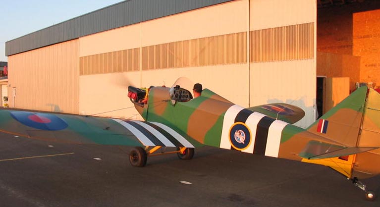
In preparation for returning the aeroplane to airworthiness, I even have an official Transport Canada variance permitting me to delete the registration marks from below my wings and for 4" marks under the tail. The variance even states quite specifically that the aircraft "shall retain its authentic camouflage replica military base paint scheme" and goes on to specify the colours, and even the invasion stripe and roundel dimensions and locations...I'm definitely "legal" now!
See the update of my paint experimentation and progress.
(February 2007)
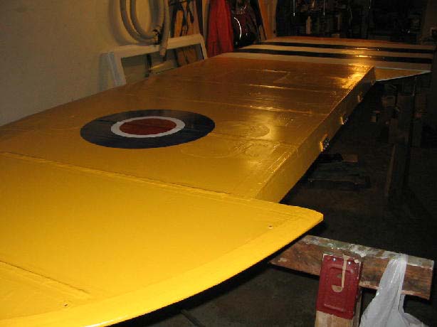
Well, I took this week off from work to give a push on finishing up Stringbag. The days have been spent out at the hanger working on the fuselage, and evenings in my basement making finishing touches to my wings. Both wings are now painted, yellow bottoms, spinach-N-sand top-sides, D-Day bands at the rots with Royal Air Force "type B" roundels on the upper surfaces, and "type C" on the undersides. I hoped to have carted them out to the airport this week, but both trailers which I had lined up became unavailable/unserviceable, and the full-size long-base van I which borrowed yesterday from a neighbour turned out to be too small as I was unwilling to stuff them in diagonally. A friend with a large hoss trailer is measuring his interior dimensions to see if it will be long enough.
My new Falcon Altimeter was installed, but was 100 feet out of adjustment, so a quick internet search found the manual on-line and I made the adjustment so that the ATIS barometric pressure matches the station altitude of 90 feet ASL.
I set up my home-built propeller balancer in the hanger, and my Sensenich woody was way out of balance, so we added a couple of coats of varnish to the rear of the light blade. A third coat was added, but we're now chasing out tails for a perfect balance (or was that blades ;)
I had previously donated my USAAF vintage compass to a friend's Fleet Finch project, so I planned to install a panel-top compass but it looked like there may be a conflict with the windscreen. Fellow Fly Baby pilot Tom Staples gave me a hand, and we installed the boot-cowl and windscreen to make sure that it would fit. It JUST clears the wind-screen and still leaves access for on panel screw. With the compass in place behind the windscreen it kinda looks like a gun-sight :P
Speaking of ol' Tom, he's been out most days this week working on engine and rigging details, and Ray White, another local (loco?) Fly Baby builder, has also been a great help assisting with the three-handed jobs on Wednesday evening and Sunday forenoon work-bees, as well as devoting an additional day this week to lending a hand.
Today, Tom and I installed the prop, rigged an oil priming pressure tank to my 0-time A-65/75. We pre-lubricated the engine with a litre of oil and gave the engine a final once-over. All looked ok, so we wheeled out the fuselage to a hard-stand, tied down the tail, chocked the tyres and I hopped in the cockpit. Fuel..on. Mags...off. Throttle..idle. Four or five shots of prime...primer locked. Tom pulled the prop through a few blades, then brakes..set, throttle...cracked, Mags...both. Tom give two swings, and there fart and puff of smoke. A few more blades, a few more puffs, but to luck. Tom was getting a bit winded, so we switched places. Second blade, and she started right up to a fast idle of 1400 rpm. Instant oil pressure, no smoke, no misses, and nice and smooth. We shut down the engine so I could adjust the throttle linkage and fix two small oil leaks.
We went through the drill again...and nothin'. A few farts, a couple of puffs, and small back-fire or two. As the engine/magneto/carb installation is all new, we had to find the engine's "sweet-spot" for priming and starting. The timing was definitely not ideal for starting. After three or four minutes of propping, there was a nasty backfire, the prop kick-back some how knocking the fingers of both my hands. Fortunately I am able to say "of" and not "off"! I have never in my 12 years of doing this ever been whacked like that, and the first thing I did was look at the fingers to see if they were still orientated in their correct directions...they were hurting like an essobee. I danced around saying owowow repeatedly but fortunately they still worked reasonably well and didn't swell up much, just some split skin, a blood blister, and a bit of leakage. At least all of the fingers didn't hurt...those ones were numb instead :)
After I settled down, Tom and decided that I definitely have to install an impulse magneto...my last engine had one and it worked great. I have a zero-time unit in my shop, but didn't have a harness for it. Thinking of things in retrospect, as I was starting non-impulse mags I had set the switches to "mags both" however I have timed the magnetos to A-75 standard where one magneto fires a couple of degrees ahead of the other...which is more advance than a standard A-65 and therefore a prime candidate for backfires.
Tom was still comfy in the cockpit (he needed the step-ladder to get out and I had yet to let him out of his cage).
I decided to give a few more blades...
She was so close to starting, and then success...she fired sup to a nice, even 1000 rpm idle. Nice and smooth, no lifter clanking...the new J-3 exhaust reasonably quiet compared to the straight 6-inch stacks of my old engine. We ran it for a few minutes and shut her down satisfied. One big step towards an operational bird again.
We secured the tools and fire extinguisher and went up to the nearby cafe for a cuppa, leaving Stringbag out on the hardstand basking in a sunbeam. I went to wash my throbbing fingers, and I could hear Tom in the restaurant explaining to the patrons who had watched the show about the benefits of impulse magnetos. We had our break, I munched on a plate of chips while listening to the amusing comments from new patrons who wandered in for lunch, speculating what kind of 'plane Stringbag was. One pilot airside wandered over for a peak, inspecting the cockpit and then the gore on his propeller blades.
 After coffee,
we pushed him back into the hanger, Tom made a few more tweaks in the engine
area, and I continued on some small electrical details. We wrapped
up things early, my fingers were hurting, but had accomplished a lot.
While I've always paid respect to engines when propping, especially ones
which I never started before, I was stung today but got away lucky.
Looking back, after my finger wrapped, I should probably have called it
a day, but I am happy with the results and an essentially snag-free which
should hopefully provide me with hours of happy service. The engine
won't be started again until I scrounge a harness and install the impulse
mag...and double-check the timing.
After coffee,
we pushed him back into the hanger, Tom made a few more tweaks in the engine
area, and I continued on some small electrical details. We wrapped
up things early, my fingers were hurting, but had accomplished a lot.
While I've always paid respect to engines when propping, especially ones
which I never started before, I was stung today but got away lucky.
Looking back, after my finger wrapped, I should probably have called it
a day, but I am happy with the results and an essentially snag-free which
should hopefully provide me with hours of happy service. The engine
won't be started again until I scrounge a harness and install the impulse
mag...and double-check the timing.
I'll have to devise a self-starter system for the engine...hand-propping is becoming "politically incorrect" nowadays at my airport anyhow.
Time for some more ibuprofen and maybe a nice nap 8:^)
Drew
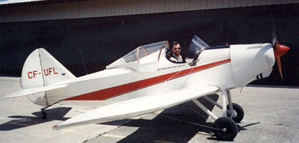
Fly Baby Mk 1a
C-FUFL
"Stringbag"
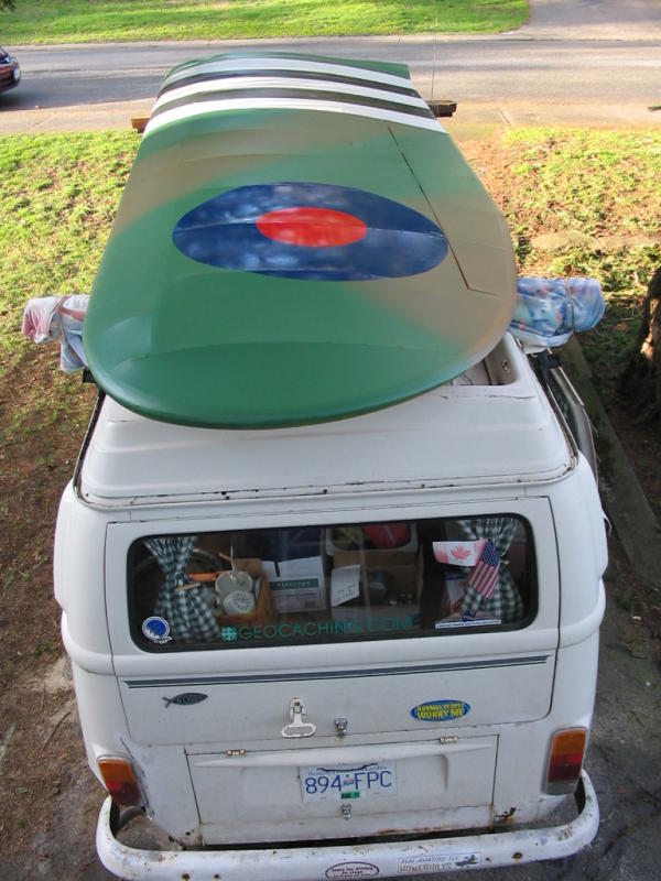
Well, after having two trailer reservations fall through and a van turn out to be too small, I made a very simple rig and transported the wings 30 kilometres out to the airport on the roof of my '72 VW bus. I made two trips, one wing per trip, via the backroads at 50 kM/h (30 mph). FB builder Ray White rode shot-gun and Tom Staples drove chase-car. I supplied FRS radios to keep in touch and those two hams provided me with some great entertainment, listening to a retired logger and displaced Englander chat. Apparently the English translation for "roger" is "jolly good" :D
All went very well, no damage, but it was a long and chilly evening motoring in my unheated bus as it started to snow during our first run out.
I rigged my roof just like I do when working on the wings when on saw-horses, I had 4X2 planks tied to the bus's roof rack tubes, and padded the rear one a flannel bedsheet supplied by Tom Staples.
The forward rack's 4X2 had a piece of plywood screwed to it, long enough to cover two rib bays regardless of position, and was able to teeter to the angle of wing's position. The plywood support was padded by a foam mat liberated from the kitchen and stapled in place.
The wing root end went forward, flat side down, with the wing tip end supported by the rear, padded 4X2, supporting the wing across the aileron spar and the main-spar/leading edge.
The wing roots were tied to the spare tyre on the front of the bus. A couple of Mexican blankets went over the top of the wings topped with a tarpolin. Gentle tension on the tarp was enough to prevent any movement of the wings.
Drew
Fly Baby Mk 1a
C-FUFL
"Stringbag"
Trying to get the Fly Baby finished has been a bit of stretch, as I've been embroiled in a major drainage do-it-yourself job at my "new" house, and among other things I lost my Wednesday evening Fly Baby work-party evening as I had to mark exams. Keen to take full advantage of this quality time spent at home, Gilligan my intrepid wonder budgie decided to complete some of his flight currency requirements with touch-and-go circuits on my head. They weren't too bad, gear down, brush through a few, thinning wires and bolter away, chirping madly. After a few of those, the carrier-style full-stops, commenced. Trying to concentrating on marking a question, I would hear him buzzing from behind, just off of the stall to chop power and drop in on his mains and breast-bone.those little guys remarkably heavy. After a few of those my humour and patience waned. Gilligan was grounded to his hanger, and I finally got finished at 23:00 that night. Maybe he was getting even for me trying to fly that newfangled RC Electric plane in the living room...
Time after work on most other evenings in the past few weeks have entailed plumbing and ditch digging, and hauling rocks about the yard.
Yesterday was much of the same, but I did manage to get some errands done. I went and updated my aviation medical (over 40 now so I now need that EKG thing too), purchased more plumbing supplies, got annoyed with the municipal planning secretary (wada ya mean you want a property survey just so I can repair a 3 foot square porch?!) and negotiated a deal with a guy for the purchase of some aircraft birch plywood ($70 for three sheets).
Today I was invited by a new, start-up flight school to display Stringbag at their open house. What the heck, I can use a break for digging and progress is slow anyhow. I made it out to the hanger early and lowered the Fly Baby off of the jacking blocks, and installed the cowlings. A few panels missing, the ailerons weren't hooked up, but what the heck, he looked presentable enough. Hanger-mate and fellow Fly Baby owner Chuck showed up to help dust off the wings, and I rolled Stringbag out of the hanger and over to the display area. Still have some slight brake drag, hopefully that pad will wear in soon. Already parked was the museum's Noorduyn Norseman, along with the local Grumman Goose and Curtis Kittyhawk.
 I took a few
pictures of Stringbag in this good company, and wandered about to mingle.
One fellow asked a few questions about the Fly Baby, and confided that
he was once an aero-mechanic for a whole year. Then he proceeded
to bring to my attention various airframe defects, no nuts on the rudder
bolts, etc. I casually mentioned, more than once, that the aeroplane
wasn't currently airworthy, but I suppose that he was just attempting to
save my life. If he looked a bit harder he may have notice the belly
pan missing, half of the controls disconnected, and...
I took a few
pictures of Stringbag in this good company, and wandered about to mingle.
One fellow asked a few questions about the Fly Baby, and confided that
he was once an aero-mechanic for a whole year. Then he proceeded
to bring to my attention various airframe defects, no nuts on the rudder
bolts, etc. I casually mentioned, more than once, that the aeroplane
wasn't currently airworthy, but I suppose that he was just attempting to
save my life. If he looked a bit harder he may have notice the belly
pan missing, half of the controls disconnected, and...
I was rescued by an old buddy who I hadn't seen around in a while. He told me that he had stopped at a small garage sale along the way to the airport, where he purchased a brand-new air speed indicator as well as a complete Westach EGT kit, still in their boxes, both for $10.
The glazed look in my eyes must have said it all, for my buddy's offer to drive me over to see if there was any more stuff didn't have to be made twice.I abandoned Stringbag on the tarmac and we scrambled for the garage sale. The sale wasn't advertised, located on a sleepy, out of the way road. It was an estate sale, everything-must-go kind of deal, the family wanted to be back on the mainland-bound ferry this weekend.
There wasn't much left, someone was loading what looked like a gasoline powered washing machine in a pick-up, a kid was toying with an Underwood portable typewriter listed for $6. I found a milk-jug half full of assorted aircraft turnbuckle barrels, forks, and eyes. Cool. I was invited to dig around the garage. On one shelf I found a set of brand-new 8" ultralight brakes, but no more instruments. I picked up the brakes. Some clear timber hanging on racks, assorted used control cables. On the workbench there was an assortment of old tools, and tobacco cans. Some held the usual old household tidbits, but in some I found treasure...used, clean WWII vintage aircraft bolts. All carefully stored by size. Silver cadmium plated, the kind with the beautifully embossed heads. Others held rod-end bearings all carefully sized and strung together, aileron bearings, old bakelite pulleys, etc. I packed them all into an old fruit crate. We put the pile of treasure down and waited for the executor to return from delivering the washing machine. Total cost was $10 for everything, which ended up including a decent a garden rake and set of old but well maintained garden shears (gotta keep my wife happy too).
Returning to the airport, I got some unusual stares, arms full gardening and aeroplane junque meandering through the guests on my way back to my hanger, a silly grin on my face.
One hanger neighbour asked me what I was up to, another snickered that I was again sniffing about for old aeroplane junque. "You want junk? one asked. He then promised to get back to me about "unloading" an float-equipped unltralight on me for $100. Only flown once, damaged nose, currently hanging in a tree (!) It even has the engine he claimed. I passed along my phone number and stumbled to my hanger with my loot.
Keeping up on my theme of the day, I scrounged a free smoky and pop from the flying school guys, chinwagged with some potential students, and answered a few more questions about Stringbag.
At 14:00 I rolled the Fly Baby back to his hanger to ready everything for the Sunday morning work party.
I collected garden tools along with some of the shinier items from my loot and wandered home. Not a lot of real "work" done today but a fun day scavenging and chin-wagging none the less.
It was a nice change of pace....
Drew
Fly Baby Mk 1a
C-FUFL
"Stringbag"
8:^)
------------------------------
The latex coatings are holding up pretty fair for a bird who is getting a lot of handling. The Armorall protectant has made the paint quite soft (I think I may have used too much too/frequently) so a few paint defects have appeared from the usual hanger rash and handling, some from abrasion and dropped tools, and a couple from what appear to be soft paint (such as when I used spring-clamps to hold an aileron in place). The coatings are quite thin, but touch-up easily. If the white latex undercoat shows, depending on the colour, and that I have a lot of, some extra care has to be taken to cover the silver-white primer but a tinted primer would have minimized this. The touch-up paint seems to adhere fine in spite of Armorall, oil for engine, etc and is applied with a bristle or foamie brush with very good results.
I have had oil spread on various latex painted surfaces from nose to tail from a leaky engine rocker box which I have had trouble with, sometimes the oil spots not being noticed for over a week, once for over two weeks. The oil simply wiped away from the Armorall treated Latex exterior semi-gloss coating. A quick clean-up with windshield washer fluid stored in a plant-sprayer bottle seems to be an effective and convenient cleaning agent.
I have twice spilled gasoline on the latex when adding fuel, once with autofuel, the other with 100LL. I wiped up the fuel, and the paint appeared a bit "dry". I then wiped down the area with windshield washer fluid and all is well, no visible scarring or distress to the paint (latex semi-gloss over alkyd enamel for the metal cowlings). I haven't got around to applying any more Armorall to the spill area yet but figure it's a good endurance test for the coatings :) This latex-over-alkyd enamel-over-primer isn't as durable to abrasion as a regular enamel or lacquer finish.
-------------------------------
The engine runs great, but I'm a bit concerned that the beautiful Sensenich W70D48 prop may be a tad too fine of a pitch for the uprated Continental A-65, as I can turn over 2150 RPM static. This is a bit quicker than the old 76-44 prop, but as the new engine has been balanced and upgraded to 75 hp standard, along with C-85 connecting rods and carburettor jetting, I'm sure that the engine can turn up enough to get me aloft.
-------------------------------
I was fortunate enough to borrow three certified scales to reweigh the aeroplane, as there has been considerable work completed and equipment changed out. After all was done, my empty weight is now a tad under 708 lbs, 22 lbs lighter than the previous Weight and Balance report that I completed some 11 years ago.
In the old configuration, the aeroplane was fitted with small 6:00-6 tyres, a canopy, pressure cowling, no electrics, and had an enamel-over-Dacron covering. The current configuration has a larger 8:00-6 tyres, Cub-style cowling, no canopy, battery/electrics/transponder, and latex-Dacron covering...both weigh-ins included fitted kit such as ELT and fire extinguisher, unusable fuel, full oil. Engine is a Continental A-65/75 with wood prop.
My Centre of Gravity calculation for the empty aeroplane is a respectable 13.7" aft of the leading edge (allowable range is 10" to 17").
Working some Weight and Balance scenarios:
For a nose heavy scenario...if a 140 lb pilot flew with full fuel (108 lbs in my case) and nothing else but a smile, C of G would be 13.3" aft of the leading edge at just over 955 lb.
For a more realistic tail heavy scenario: if a 180 lb person (me) loaded up with 40 lbs of clothing, kit, charts, peanut butter sandwiches, a belly full o' pancakes etc, and flew with 30 lbs of Fly Mart loot evenly spread in the baggage compartment and only 5 gallons of fuel in the tank...I would still be within the aft C of G limit at a tad over 100 lbs...and as my maximum allowable take-off weight is 1060 lbs, there would still be considerable useful load remaining (hopefully for more fuel).
-------------------------------
I hope to finish up the small details this week so I can commence some runway taxi time, and plan to taxi Stringbag over to the BC Aviation Museum's open house this Saturday. So, makin' progress, in spite of w*#k and my home renovations!
Cheers,
Drew
Fly Baby Mk 1a
CF-UFL
"Stringbag"
FROM: DOGSBODY
ACTION: FLYBABYLIST
INFO: BCC
SUBJ: FIRST FLIGHT FLY BABY CF-UFL
REF: NIL
1. AFTER THOROUGH TAXI AND GROUND HANDLING TRIALS FLY BABY CF-UFL HAD A QUOTE SUCCESSFUL FIRST FLIGHT UNQUOTE TODAY AT 1500Z, THE FIRST TIME A/C AIRBORNE IN OVER 10 YEARS
2. DETAILS OF FLIGHT ARE AS FOLLOWS
 A.
A/C LIFTED OFF WAS SOMEWHERE IN VICINITY OF 50 KTS IAS, DIRECTIONAL CONTROL
AND INITIAL ACCELERATION SATISFACTORY
A.
A/C LIFTED OFF WAS SOMEWHERE IN VICINITY OF 50 KTS IAS, DIRECTIONAL CONTROL
AND INITIAL ACCELERATION SATISFACTORY
B. A/C CLIMBED INITIALLY TO 100 FT AGL TO ASSESS HANDLING AND RIGGING. WHILE SLIGHT FORWARD PRESSURE WAS REQUIRED ON STICK, YAW AND ROLL TRIM WERE QUOTE PERFECT UNQUOTE SO FLIGHT WAS CONTINUED WITH A FULL CIRCUIT FLOWN
C. A/C CAUTIOUSLY CLIMBED TO CCT ALT AS INTREPID TEST PILOT (ITP). 80 KTS INDICATED ON DOWNWIND AT APPROX 2500 RPM. CONTROLS WERE LIGHT AND WELL BALANCED, AND ENGINE RAN FLAWLESSLY. OPEN COCKPIT WAS SURPRISINGLY QUIET AND DRAFT FREE
D. FIRST LANDING FAIR, WHILE ITP WAS A BIT FRIGHTENED HE WAS NOT SCARED. AFTER A FEW BOBBLES AND MINOR CORRECTIONS JUST OFF STALL IN GROUND EFFECT A/C THREE POINTED ON RUNWAY IN PROPER CARRIER FASHION. WHILE CLOSE-APPROACH SPEED OF 60 KTS IAS WAS MAINTAINED, ITP DID NOT NOTE ACTUAL LANDING SPEED. AFTER THIS SINGLE CCT, ITP CHOSE NOT TO PRESS HIS LUCK AND RETURNED A/C TO HANGER IN ORDER TO CONSUME COLD FROSTY BEVERAGE
3. POST FLIGHT INSPECTION REVEALED NO DEFECTS, HOWEVER TWR REPORTED ALTITUDE ENCODER U/S. IN ADDITION, A/C SOILED BY GUANO DURING RETURN TAXI BY LARGE FLOCK RECALCITRANT CANADA GEESE FLUSHED OFF OF TAXIWAY BY A/C
4. A SINCERE THANK-YOU TO ALL WHO ASSISTED WITH PARTS, ADVICE, AND MORAL SUPPORT IN THE RESTORATION OF MY STRINGBAG
5. DOGSBODY SENDS
[Editor's addendum: Yeeeeeeeehaaaaaaaaaa!]
 Goal
Achieved
Goal
AchievedThe day started out foggy, and work was very busy. Whenever I got a chance I poked my head out doors to (as Ron has so ably phrased it) "Sniff the Wind". Visibility was poor with low ceilings and drifting fogbanks. As the afternoon wore on blue sky could be seen through the wisps, but the fog was stubborn. This in itself isn't too serious of an issue here in my locale, as while the inner harbour often gets socked in, just a few klicks up the peninsula the airport will often be clear.
At the end of the day I secured the shop and zipped home to collect my flight kit. I stopped to fill up a couple of gas cans and was soon on the highway northbound. Blue sky started poking through and soon visibility was clear with a slight haze.looks like I'll get some flyin' in!
Arriving at the airport I was casually greeted by Knuckles the Hanger Cat. After a quick "hello.got any fude?" he reassumed his duties as gate guardian, flopping onto his starboard side so as to better display his pot-belly in a brazen act of intimidation.
 Rounding the
corner I found Tom's Fly Baby C-GJTS parked in front ready for scramble,
with Tom and Fly Baby owner/hanger-mate Chuck enjoying the sunshine and
BeeEssing over sodas.
Rounding the
corner I found Tom's Fly Baby C-GJTS parked in front ready for scramble,
with Tom and Fly Baby owner/hanger-mate Chuck enjoying the sunshine and
BeeEssing over sodas.
I fuelled Stringbag, made my walkaround, and called for my transponder code. Put on the Mae West, too warm for the fleece-lined flight-suit today. Preposition my charts and kneeboard in the cockpit..time to fly!
Holding at November I make my call in, taking pains to identify my exact position on the 'field (so the Ground Guy can spot me in spite of Stringbag's cammo paint job), and receive permission to taxi.
Tom does the same, but there's a minor kafuffle as Tom isn't at his normal dispersal point.
We taxi across Runway "2-0" and onto the north-side perimeter track, holding at one point to allow our buddy in his VariEze to taxi to his hanger. I'm blind as a bat in the three-point.
We line up side-by-side on Kilo for our run-ups:
A call to Inner Tower and I'm off: power up, stick forward. Tail raises nearly immediately.right rudder to check the swing.and at high-30-something-knots Stringbag unsticks. As I'm rolling Tom is cleared for take-off in sequence.
We're cleared for the Cordova Bay departure for local South, Flight Level 2.0.
 At 1000
feet on a cross-wind departure I call Outer Tower:
At 1000
feet on a cross-wind departure I call Outer Tower:
"Outer Tower, Charlie Foxtrot Uniform Fox Lima through one-thousand for Two thousand".
Outer Tower reports my encoder not functioning (again). Dang.just got it fixed (again).
Tom is now on my port wing.
We level at 2000' and Tom crosses over to my Starboard and assumes lead. I tuck in and we cruise toward the city. The fog is still there obscuring the Inner Harbour. Otherwise visibility is 30 mile in haze.
A Turbo Otter on floats transits to our west. Those are the prettiest working 'planes in the harbour, IMHO.
Outer Tower calls and clears us out of their zone. I switch to Harbour Radio and call in, requesting to transit their CZ, "Special VFR.clear of cloud". Harbour Radio adamantly denies my request..."zone is IFR". Hmmph. While the Inner Harbour is socked in most of the zone is clear.
They let us transit last week in similar conditions, but this nice man in the fog bank swears the zone is IFR. We must have interrupted his supper :) Instead of arguing the point (not like someone I know who did laaaast weeeek) I signed off and turned west.
Tom is now tucked on my starboard wing. Instead of flying the hills to skirt the zone I call Outer Tower back and inform them that we'll be flying on the southern edge of their zone and will remain on their frequency for traffic.
Tom and I fly about in loose formation, eventually straying a bit far over water. I waggle and turn inland away from him. Keeping my head on the swivel I suddenly see the FB-109 break towards my tail. I power up and tighten my turn.time for some jousting!
We made three orbits, with Stringbag slowly gaining on the Wiley Staples' tail.both maintaining altitude. Air is dead smooth. Sunbeams occasionally glinting off of his canopy. This is what flying is all about! Tom levels out and I tuck back into formation.
Soon Tom waggled and broke off, heading into the hills. I puttered about enjoying the sights and circled the Gardens. In our post-flight debrief, it seems that Tom decided to hold off for a "Drainage Trial". If anyone has ever noticed a jar covering Tom's fuel tank cap-vent.I highly recommend the use of gloves prior to handling it.
What a great evening! Listening to Outer Tower frequency they were getting busy. A shortage of controllers has led to VFR restrictions, and this evening they were busy as the Grumman Tracker fire retardant bombers are actively working. The tower had VFR flights orbiting while they got the IFR sched's in.
Tom re-emerged from the hills, requesting clearance for re-entering the zone for landing. I checked ATIS and followed suit, being vectored across the arm to follow mountain highway route astern of Tom in his FB-109. What I great evening. I increased the separation between Tom and myself. They had Tom stooge about in a 270 short of 0-2 to facilitate another IFR take-off. Cleared to land, he requested a go-around.
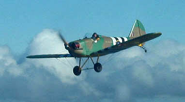 I'm now #1.
Making my approach at 65 KIAS, a bright red and white painted Tracker idles
to the side awaiting take-off. Cool. I made a fair, cross-wind
wheel landing, "stirring the pot" and keeping the tootsies active in yet
another successful attempt of not making a fool of myself.
I'm now #1.
Making my approach at 65 KIAS, a bright red and white painted Tracker idles
to the side awaiting take-off. Cool. I made a fair, cross-wind
wheel landing, "stirring the pot" and keeping the tootsies active in yet
another successful attempt of not making a fool of myself.
I expedited my exit and the Tracker was immediately cleared for take-off, retracting his gear has he thundered past my left quarter.
*sigh*
After securing Stringbag, Tom drove over from his hanger to pick me up, and we grabbed some McTake-out. Returning to the hanger we retired to the comfort of the lawn chairs. We watched the circuit, happily chatting and munching our cheeseburgers while the sun set behind the hills.
Fun Flyin'!
Drew
Many thanks to Drew!
 Return
to the Fly Baby Tech Talk Page
Return
to the Fly Baby Tech Talk Page