 Well...keep in
mind that I'm not an aeronautical engineer, and I never spoke to Pete about
other ways of doing it. But let me give you some of my thoughts on
the subject of alternate wing-bracing systems.
Well...keep in
mind that I'm not an aeronautical engineer, and I never spoke to Pete about
other ways of doing it. But let me give you some of my thoughts on
the subject of alternate wing-bracing systems.
>I think the flybaby is a great design except for all those wires.
I
>understand the reason Mr. Bowers designed the Flybaby with all
those
>wires was for the purpose of quickly detaching the wings
for easy
>transport of the aircraft. I would just prefer a set of struts
on both
>sides, because I don't need to disassemble the wings. But
I quess if we
>did that we would have to redesign the landing gear. Am I
too
>concerned about all those wires?
Well...keep in
mind that I'm not an aeronautical engineer, and I never spoke to Pete about
other ways of doing it. But let me give you some of my thoughts on
the subject of alternate wing-bracing systems.
When a person designs an aircraft, the primary thing in their mind is usually the mission of the aircraft...what it's going to be used for. The Fly Baby was designed to a rather unique mission: Winning the EAA Design Contest. Performance wasn't a major issue; the primary goal was an easy-to-fly airplane that was simple to construct, didn't cost much to build, and was trailerable.
There are three basic choices for any wing system: Cantilever wings (like a Piper Cherokee), strut-braced (like a Cessna 172), and wire-braced (like the Gee Bee). Let's look at each in turn.
But they aren't truly simple. They put a heck of a lot of load on the wing root and spar carry-through section in the wing root. Typically, there's a set of pins (usually big bolts) holding the wing to the fuselage, oriented horizontally, at the top and bottom of the spar. In flight, the wing is trying to pivot around the lower pin and snip the top one (this is a simplification). The pin and fittings have to be very strong, and the further apart the top and bottom pin are, the less actual load on the top pin. The same holds true with the area on the fuselage the wing attaches to, too.... the carry-through has to be able to withstand the incredible loads put onto the wing spar pins.
But this is just plain 'ol engineering... thousands of designers have handled the problem successfully.
However, the *manufacturing* of the wing root/carry-through area is a bear. Each wing root of a small aircraft typically has three or four of these spar pins, and if their mounting holes are off by a few thousandths, the wing won't fit!
Ask an RV builder about drilling the spar pin holes on their wings. You'll either get a shudder, and an explanation of all the precautions and care they took. For a buddy of mine with an RV-7, this was a week-long nerve-wracking process. Or you'll get an odd look, and a "Well, they came already done in my kit."
Obviously, when it comes down to designing a plane where there WON'T be a kit available, and the plane is going to be built by thousands of over-enthusiastic amateurs, a cantilever wing is probably not the right way to go. Not only may many builders get frustrated with trying to make the precision fittings necessary, many may also take short cuts or kludge up fixes when they drill the holes wrong.
A classic example of this can be found in one of Van's other designs, the RV-3. The single-seat RV has had a large number of wing-failure accidents traced to builder error. One spar-attach point has very little edge margin; if the builder didn't do it exactly right, the wing might separate during acrobatic flight. Here's an FAA bulletin, back from the 80s.
BUILT right, the plane didn't have a problem. But the original spar attach design was not sufficiently tolerant of error, corrosion, or improperly-done repairs. Van came up with a fix for this (the RV-3A). But it does illustrate how design of an amateur-built aircraft has to include significant tolerance for bad construction.
And, obviously, a cantilever wing wasn't the best choice for a plane that's supposed to be easy to built. Not everyone agrees with that...of the six aircraft competing in the 1962 EAA Design Contest, two *were* cantilever-winged.
But when it came to evaluations, the Fly Baby's simplicity took the cake. Of the second-place finisher, the Turner T-40, the EAA magazine report said, "The wing structure was somewhat more complex than an externally braced wing, as was to be expected. It also necessitated precision fit spar fittings and bolts."
The Fly Baby, on the other hand..."Structural simplicity, non-critical components, and clear drawings recommend this airplane for a beginning builder."
As a final comment on cantilever wings, doing one in wood usually necessitates a box spar. This is not a simple object, as this photo of the Loehle 5151 Mustang shows:
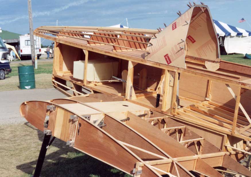
The Loehle uses a plank-type aft spar, but the huge box spar is quickly apparent...the light colored area with the hole is the top of the main spar.
Compare that to the Fly Baby's simple 3/4" thick plank spars. Wooden box spars also have issues with collecting water on the INSIDE, which triggers rot and is generally impossible to detect, and with difficulties ensuring sufficient glue coverage. Knute Rockne's death in a Fokker Trimotor triggered an investigation that lead to the outright banning of wooden box spars in transport-category aircraft. Here's what the Department of Commerce inspector wrote:
"The wing broke off upwards, under compression. Examination of these [wing] parts showed that in the upper and lower laminated portions of the box spars, some places the glued joints broke loose very clean, showing no cohesion of the pieces of wood....Federal inspectors, after stripping off the skin of one F-10 wing, discovered moisture accumulating in the interior had caused deterioration of the glue, materially decreasing the strength."
As a final note about cantilever wings on Fly Babies, remember I mentioned earlier that the top and bottom attach pins need to be widely spaced. This means a deeper wing section...which in turn, would mean the plane needs an entire new airfoil! It's really no longer a Fly Baby.
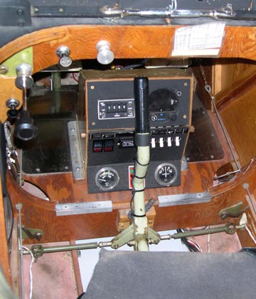 In addition,
the Bulkhead 3 and 5 wing-attach points are currently just designed for
single pins. The lower carry-through of both bulkheads would have to be
extended upward by several inches to give enough area to allow attachment
of two vertically-oriented wing-spar pins. Bulkhead 3 is where the
pilot's legs stick through...making the lower leg of the bulkhead six inches
higher would really complicate the seating position. Note the current
single-spar pins at the bottom of this photo of Bulkhead 3. A cantilever
wing would require a second set of pins about eight inches above the current
set...and there has to be considerable clearance from the corner curves.
The pilot's legroom would be severely limited.
In addition,
the Bulkhead 3 and 5 wing-attach points are currently just designed for
single pins. The lower carry-through of both bulkheads would have to be
extended upward by several inches to give enough area to allow attachment
of two vertically-oriented wing-spar pins. Bulkhead 3 is where the
pilot's legs stick through...making the lower leg of the bulkhead six inches
higher would really complicate the seating position. Note the current
single-spar pins at the bottom of this photo of Bulkhead 3. A cantilever
wing would require a second set of pins about eight inches above the current
set...and there has to be considerable clearance from the corner curves.
The pilot's legroom would be severely limited.
So...why didn't Pete use struts instead of wires?
A couple of reasons, I think. Strut-bracing is ideal for high-winged aircraft, but I don't believe Pete wanted a high-winger. In the first place, the Les Long's trade studies in the 1930s established that the most efficient configuration for a low-powered aircraft was with a low wing.
Second...well, remember, Pete was six feet two inches (1.9 meter) tall. When you're that big, visibility absolutely stinks out of a high-wing aircraft. I'm only six feet, but when I sit in something like an Avid Flyer, turning my head to the sides only gives me a view of wing root. Designing a high-wing aircraft with decent visibility for tall people would mean a fairly deep fuselage...and the visibility still wouldn't be that good. Pete had been flying the Story Special for several years, and I think he probably was spoiled with the great visibility a low-wing single-seater offers.
There are two basic choices, when it comes down to strut position: On top of the wing, attaching at the landing-wire terminal position, and below the wing, attaching to the landing gear like the current flying-wires attach.
There have been Fly Babies built with struts in either location. Pete didn't like the ones with the struts below, though. If I remember correctly, he worried that sideloads applied to the landing gear tend to stress the wing mountings. On a normal Fly Baby, the flying wire/landing wire/landing gear combination form a closed-loop system that opposes the loads without concentrating them in one point.
With this system, if the gear gets pushed to the right, the sideload is opposed by the cross-wires in the landing gear and the landing wire attachment on the left wing. With struts, the wing still gets pulled, but there's nothing to opposite it but the landing gear cross-wires. Pete apparently didn't like seeing the wing-attach system stressed like that.
So, why not do struts on TOP on a low-wing aircraft?
Bad aerodynamics, for one. When two objects join, the amount of intersection drag depends on the angle they join at. Minimal drag is at 90 degrees, and the drag just goes up from there. Usually, designers compensate for the non-90 degree interface by using fairings that get bigger the faster the plane goes and the difference from the ideal 90 degree position.
For a great example of this, compare the F4U Corsair with other WWII planes. The Corsair has inverted gull wings to minimize the length of the landing gear, but the inverted-gull arrangement ALSO resulted in the wing coming off the fuselage at exactly a 90-degree angle. The Corsair has next to no wing-root fairing. Compare it with a P-51 Mustang, which has a pretty big fairing just to cut down the drag from a few degrees of dihedral angle.
A strut on the top of a long-wing intersects the wing at a *very* shallow angle. There's going to drag. There's also going to be turblence...and that's not what you want, on top of the wing.
One of the Fly Baby's competitors in the EAA Design Contest was the Spezio Tuholer, a low-wing tandem two-seater with the wings braced with struts on top. One of the reasons it didn't win, according the EAA magazine writeup:
"...its stalling characteristics indicate that additional work may be required before releasing the airplane to the average pilot...."
There was undoubtedly more at work here than just the intersection drag, but the turbulence associated with the wing struts probably didn't help.
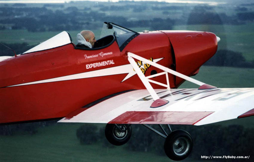
Argentinean Pablo Tschopp built a Fly Baby with top struts. We don't know if the aircraft performance handling were affected. As far as I know, Sr. Tschopp had never flown an unmodified Fly Baby, and no one with Fly Baby experience had ever flown his. It may have not changed the handling significantly. But the stock Fly Baby does have a rather sharp stall break, and I suspect the struts won't have helped this any.
However, keep in mind that this *wasn't* a simple modification. It was not as complex as a cantilever wing was, and probably a lot more doable, but this wasn't just the case of bolting a set of struts in place. Tschopp's modification involved considerable reinforcement of the bulkhead 3 landing-wire attachment area. If I remember correctly, it included a set of welded steel-tube Vees mounted upside down at Bulkhead 3, along with some bracing across the cockpit. The stock Station 3 Bulkhead sees only compression loads in flight, and the change to a strut changes this into tension loads.
So it's not just as simple as bolting a set of struts in place.
Pete didn't invent this, of course. It was used by a number of aircraft, including the famous Gee Bees.
I don't think the wing-folding requirement drove Pete to the wire-bracing system. Remember, he'd been flying the Story for several years, and it has a wire-bracing system (although its wings don't fold). None of the other competitors used wires...three used struts, two were cantilever.
Why a wire-braced system, then? It's easy to build, it's light and, in an era of cheap surplus parts like turnbuckles, it was cheap. Like any wing-attach system, it's subject to problems when the builders or maintainers make mistakes. Just like you can't blame Van when RV-3 builders didn't leave enough edge margin for their spar mounts, you can't blame Pete when Fly Baby builders use pliers to crimp nicopress fittings.
Three great aspects of the wire-bracing system: First, nearly *everything* is wide out in the open. Cantilever wings and wing struts can hide corrosion or rot inside, and you may not be able to inspect them fully even at annual time. With the Fly Baby, it's all right out where you can see it during preflight. A simple set of inspection panels even let you check out the attach points on the wings.
Second, once you've paid for the turnbuckles, everything else is cheap. Worry about the wires corroding? Fine, replace them every five years like Tom Staples does. Inspect and re-use the turnbuckles, and the cable, nicopress fittings, and thimbles will probably run less than $100.
The final advantage...well, it sounds purty in flight. :-)
As I've mentioned before, I recommend folks use Pete's alternate method of wing-wire attachment, but the stock plate system is certainly adequate. In any case it's right out in the open, ready for inspection at any time.
Anyway, that about dumps my limited store of wing-attachment knowledge.
Anybody with any better insight, please chime in!
 Return
to the Fly Baby Tech Talk Page
Return
to the Fly Baby Tech Talk Page