[Webmaster's note: One of
the first things we learned when we started to fly was how you had to
crank on the elevator trim system every time you changed power settings
or airspeeds. I get a lot of shocked looks from folks at Fly-Ins
when I point out that my Fly Baby doesn't have a trim system... just
a metal fixed tab on the tail. The Fly Baby is so light on the
controls that, once the fixed tab is set properly, the control
pressures never get very high. I can fly touch-and-goes all day
never feeling that I'm fighting the stick.
However, as Chuck points out, the trim pressure on a Fly Baby does change during cross-countries (due to the fuel burning off). This is never more than a slight irritant...but it IS an irritant. He wanted to be able to adjust for the pressure change, and developed this nifty little trim system to let him do so.
My main point is that a trim
system is practically mandatory for most airplanes, but not on Fly Babies.
Don't think you have to add a trim system just because the Cessna or
Piper you learned to fly on had one. Chuck's system is great in
that it can be easily added after
construction...if you decide you really need one, after all. --
Ron Wanttaja]
I completed my Flybaby (N7627C) and flew it for
the first
time in September, 2008. The project
took eight years, and I thoroughly enjoyed the building and learned a
great
deal along the way. Flying a plane that
you have built yourself is extremely satisfying. I
have about 65 hours on my baby now, and
feel right at home. It’s a real blast to
fly, kind of like a flying motorcycle.
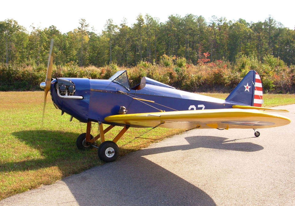
With a fixed trim tab on the elevator, my plane
flew hands
off in cruise, but I found that after about an hour in the air, forward
pressure was required on the stick to keep it from climbing due to the
reduced
fuel load forward of the CG.
Additionally, when throttling back on base, aft pressure was of
course
required to glide at a slower speed.
Stick pressures are so light on a Flybaby that this is little
more than
an annoyance, but there is something truly sublime about an airplane
that will
fly itself in all flight regimes, so I thought I’d look into adding
adjustable
trim.
Since I didn’t want to cut into my beautiful
fabric job to
install an aerodynamic system in the tail, I decided to develop a
“spring
system” inspired by one in a friend’s Piper Pawnee.
The beauty of this approach is that the
system can be entirely installed in the cockpit area, and doesn’t call
for any
alteration of the elevator controls or
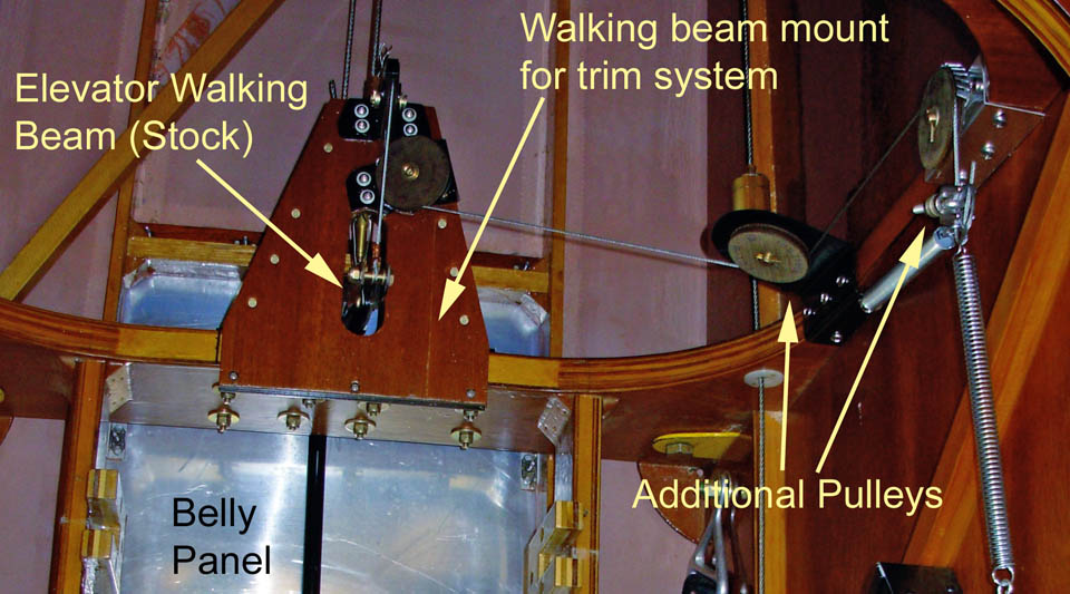
cables. The system sort of rides along
on the existing walking beam located just behind the pilot’s seat at
Sta.
5.
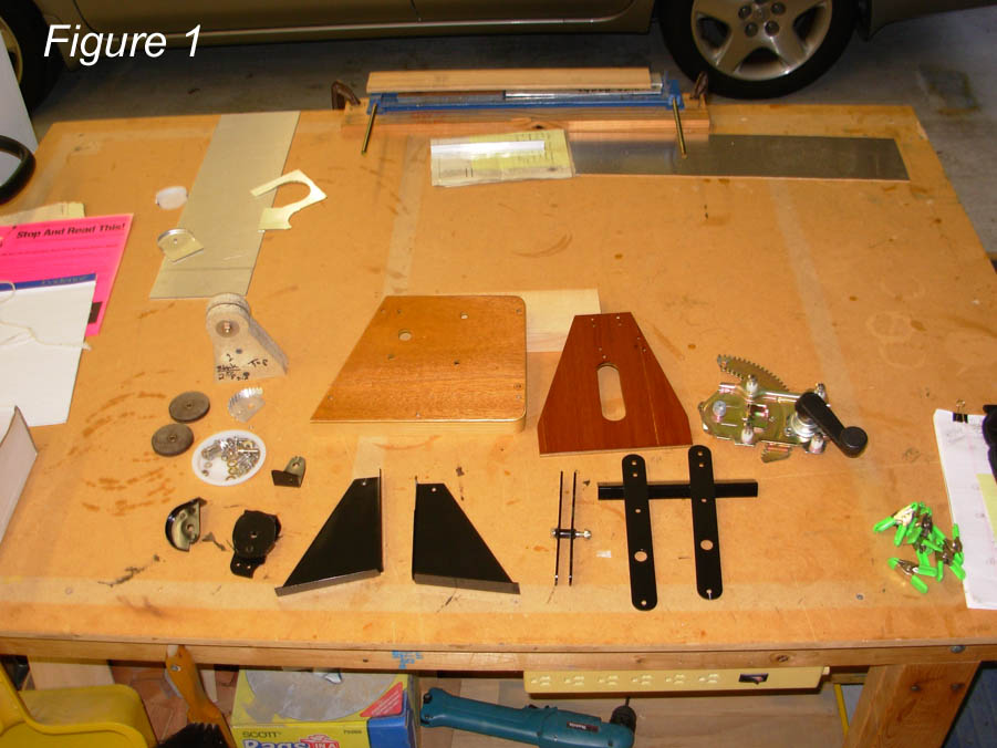
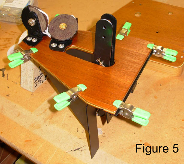
The trim system consists of three main components or assemblies. The crank box which is mounted on the port fuselage side under the throttle, the Sta. 5 walking beam mount with its cutout for the extended walking beam “ears” located just behind the pilot’s seat, and the two directional pulleys that lead the cable from the walking beam mount to the crank box. (see fig. 1 for a picture of all components).
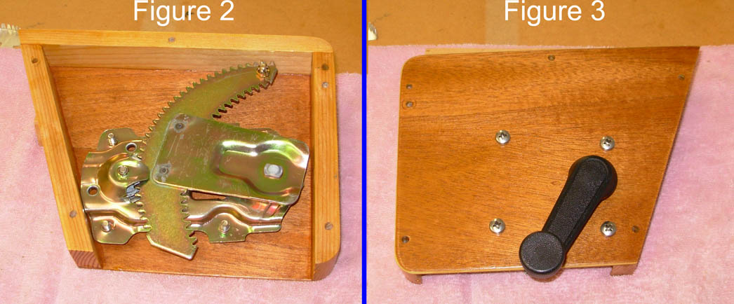
The crank assembly ( fig. 2) is simply a 1/8”
plywood box
with spruce framing sized to hold a 1976 Datsun pickup truck window
regulator. You can find new
aftermarket
regulators on the internet for about $20 – just saw off the part you
don’t
need. I’m sure any number of regulators
would work, the Datsun one just looked to be about the right size, and
was. (
fig. 3)
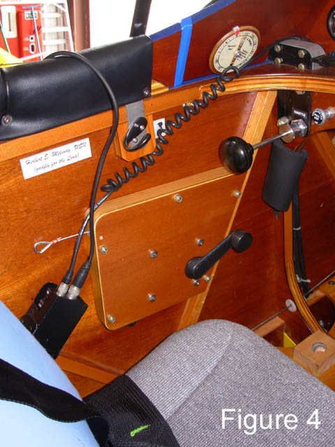 There is room next to my left leg to crank the handle,
and it is low
enough not to interfere with the throttle (Figure 4)
There is room next to my left leg to crank the handle,
and it is low
enough not to interfere with the throttle (Figure 4)The third component, for lack of a better term,
consists of
the two directional pulleys mounted on the Sta. 5 vertical that route
the cable
to the crank box. Since the lower of the
two mounts stands off more and is less supported than the other mounts,
I made
it out of chromoly – the others are aluminum.
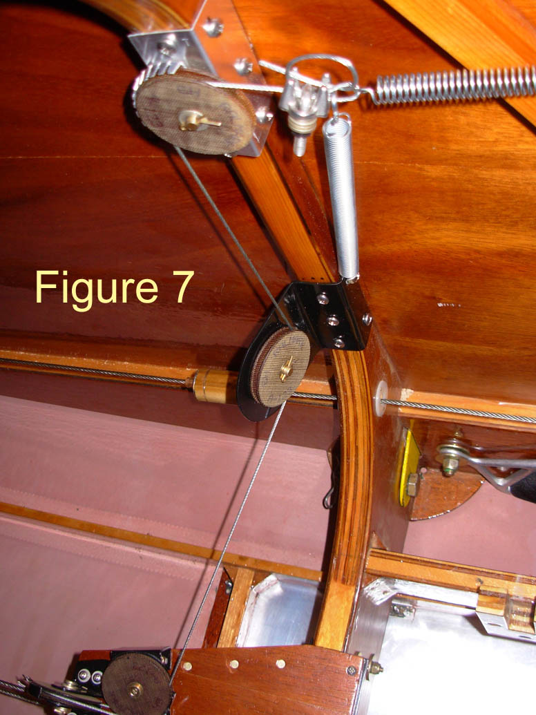
The springs are the final touch – you’ll see that
there are
two. (fig. 7) The horizontal (trim)
spring creates the tension that raises or lowers the nose when you
crank the
crank. (You need a spring in the system
as opposed to just a solid cable so that you can override a trimmed setting to dive or climb from the
trimmed position – think about it a minute.)
The vertical spring’s only function is to take up any slack in
the cable
when the nose is trimmed way down and the stick is pulled all the way
back. This is a safeguard against
the
cable jumping the pulleys, perhaps not really necessary with the pulley
guards
in place. I did not put an opposing
spring in the system for nose down trim, although this could be added. Instead, I have set the existing fixed tab on
the elevator to provide the nose down force just necessary for level
flight
when getting very low on fuel – this proved to be a very slight
deflection of
the tab, so not much drag. (Or at least
not enough for me to go to the trouble of figuring out how to mount a
second
trim spring) I tried a couple of springs
before I found the one that was just right to serve as the horizontal
trim
spring – it came from Home Depot. The
one that proved to be just right has a pull of about 3.6 lbs, the first
one I
tried at 2.1 lbs was too light. The
vertical spring can be very light, as again it just takes up the slack
when
there is no pull on the cable. Given a
Flybaby’s light stick forces, the trim spring is only required to exert
a
moderate pull and is easily overridden even when the aircraft is
trimmed full
nose up – an important consideration.
For a Flybaby that has a belly
panel like mine, this is a
very doable project. I was able to work
from a creeper below, and then from the top by sitting backwards in the
cockpit
on the floor. By the way, the Pawnee
system utilizes a cable that runs directly from the crank box all the
way back
to a spring on the elevator horn, but it’s so tight back there in a
completed
Flybaby that I thought working with the walking beam was the way to go. The walking beam approach is necessarily more
complex, but there’s plenty of space to work in, and you don’t have to
cut into
anything.
How does it work?
Like a champ. As the fuel burns
off, just give it a crank forward, and it settles back down to level
flight. Crank it back a turn or two when
you reduce power for base, and it comes down hands off at 65 mph likes
it’s on
rails. Don’t you love an airplane that
will do that?
Disclaimer: The
foregoing is provided only as information that may be of interest to
Flybaby
owner/builders. I am just a builder, not
an engineer. If you intend to utilize a
system based on this approach, I would
suggest having it inspected by an A&P with Inspection
Authorization, or at
least an EAA Technical Inspector.
June 2009
