(Updated with important notes - July 2015 and December
2019. See info at end)
When I told the guys on the Fly Baby mailing list that my next magazine article would be about how to mount a handheld radio in the panel of an aircraft, some were a bit skeptical. Harry Fenton commented, "If you can write an entire article on slapping a piece of Velcro between the radio and the panel, you deserve every cent that you are paid!"
Well—the latter half, at least, remains to be seen.
Many owners of lower-cost homebuilts and classic airplanes use handhelds as the primary communications device. Most of them, indeed, just slap a Velcro strip or a ty-wrap to hold the radio in place.
Not me, though. My handheld is flush-mounted behind the panel with aluminum channel, a configuration I've dubbed, "Full Metal Velcro." We'll discuss the "hows" in a moment—most of you are probably curious about the "why."
Well, Why?
 Why?
Well,
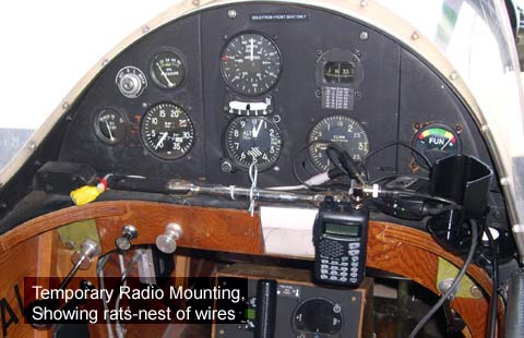
I hate cluttered cockpits. I dislike the exposed cables and
wires that are part-and-parcel of "temporary" radio
mountings. They look bad, and there's always the danger of
snagging a wire when entering or exiting the cabin.
Why?
Well,
I hate cluttered cockpits. I dislike the exposed cables and
wires that are part-and-parcel of "temporary" radio
mountings. They look bad, and there's always the danger of
snagging a wire when entering or exiting the cabin.
Also, the Fly Baby is an open-cockpit airplane. Prudence dictates disconnecting and removing the radio whenever the plane would be left unattended, be it for a fly-in or a $100 hamburger. Yet another hassle.
Finally—well, I'm cheap. When my old round Narco finally gave up the ghost, the lowest price I found for a "real" aircraft radio was about $700. The ICOM sold for less than a third of that price. I was actually standing outside the vendor booth at Arlington, reaching for my wallet to buy a brand-new "real" radio, but my intrinsic stinginess reared its head. Doggone it, I at least wanted to try to adapt a handheld!
The main design goal was to install a handheld radio so that its functionality was identical to that of a conventional aircraft radio. It would be powered by the aircraft electrical system, would provide conventional headset jacks, and use the existing stick-mounted push-to-talk switch.
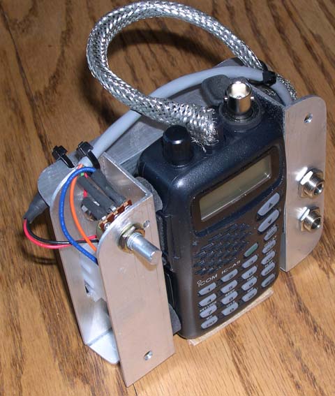
I selected the ICOM IC-A5 radio due to its very small size. Most handhelds are fairly lengthy, consisting of a display area, keypad, and speaker/battery area, but the A5 packs everything into a ~4" tall main unit. ICOM apparently no longer produces the A5, but similar techniques can be used to install other handheld radios.
I found an eliminator for the ICOM from Batteries America – part number CBE-200, $25 plus shipping. It came with a long, coiled cord ending in a cigarette lighter plug. I didn't need the plug, so I lopped off most of the cord, leaving just eight inches or so.
The biggest problem was in stripping the outer, molded plastic sheathing from the two power wires contained within. The sheathing was very soft and stretchy—very hard to cut open with a mechanical stripper.
The core wires, once exposed, were red and white, vs. the usual red (positive) and black (negative). Testing with a voltmeter confirmed that the red was still positive, and the white wire was negative.
Unfortunately, the power wires were surprisingly fine (24 or 26
gauge)—and, unfortunately, fragile. It turned out that one
of the wires had broken when I manhandled the cable, trying to
strip off the sheathing. I bit the bullet and bought a
second eliminator. This time, I carefully stripped away the
sheathing with a razor knife, and all came out OK.
The adaptor cost $60, and I was loath to cut it up for my panel-mount attempt. The plug used on the ICOM is a four-conductor 3.5mm unit. RT Systems part number CT-53R fit the bill, and it came with the wires already molded in place. It cost just $8 and shipping. The same plug is used on camcorders, so your local video shop will have cables that you can cannibalize.
Using an ohmmeter on the ICOM adaptor, I found the connections to the plug were as follows:
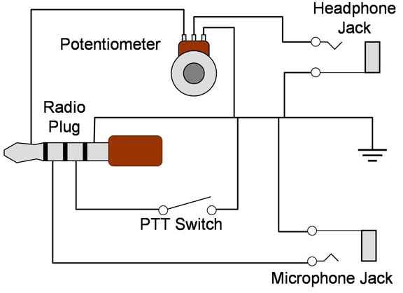
The ICOM's software let the user select which way the radio worked…knob for tuning, front buttons for volume, or knob for volume and buttons for tuning. I decided to make the inaccessible knob the volume control, and use a separate potentiometer (or "pot" to wireheads) to control the headset volume. By turning the ICOM volume control to maximum prior to installation, I'd be able to control the headset volume with a panel-mounted 10K potentiometer from the local mall electronics store.
Be advised, though, that incorrect wiring of this pot can damage the radio. The pot has three solder lugs, side-by side. A ground wire goes to one of the outer lugs, and the earphone wire from the radio goes to the OTHER outside lug. The headset jack itself is then wired from the ground and the MIDDLE lug.
To make the volume control work in the conventional direction (e.g., turn right to increase the volume), look at the pot from the side with the shaft, and the line of lugs on top. In this attitude, the ground should be connected to the outside lug on the right.
But of course, if this were before computers, I'd be sitting here wrestling with an inky ribbon, gallons of Wite-Out, and twenty-five pounds of cranky Underwood typewriter. From that point in view, coming up with a way to solidly mount the melted-brick shape of the ICOM into panel didn't seem so bad.
The mounting concept is to clamp the unit to a
slightly-undersized opening in the panel. I did some
measurements and came up with a template to use for the
hole. Printing out the templates on card stock let me cut
out test pieces for trial fit on the radio. Cutting a hole
big enough for the whole radio face wasn't an option. A hole
that bit would press the antenna coax jack against the back of the
panel, making it impossible to connect an antenna.
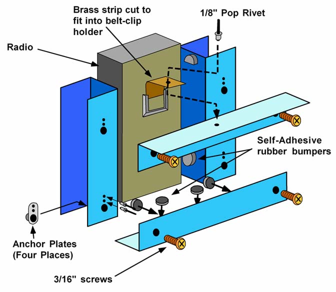
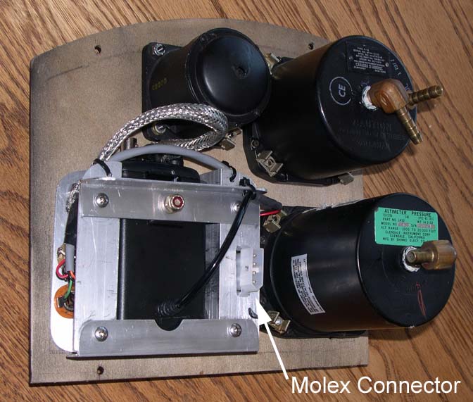
The basic bracket consists of two parallel rails of aluminum channel, cut from 1.25" square, 1/16" wall aluminum tubing. The rail on the left side of the radio had to stand away from the case, since the radio's built-in push to talk switch was mounted there. Self-stick rubber bumpers from the hardware store did the trick, with a strip of thin felt padding on the other side. The side rails were also used to hold the headset jacks and the volume-control potentiometer, resulting in a very compact installation.
The rails were held tight against the radio by two cross-braces of aluminum angle. The adhesive on the bumpers obviously can't be trusted in the long term, but they only had to stick to allow assembly. Since the rails and cross-braces clamp the radio, they pin the pads in place.
One cross-brace went at the bottom, to prevent the radio from sliding down. However, because of the cable jacks and knobs at the top of the radio, a similar brace cannot be installed there.
My first thought was to run a bolt through the battery eliminator into the cross-brace. Using the "poor-man's X-Ray" (very small drill bit), I determined that there was no electronics near the top of the eliminator around the mount for the belt clip. Running a bolt from the inside the eliminator through the brace did the trick.
Unfortunately, when I mangled the wires to the eliminator and had to replace it, I faced the prospect of trying to drill a hole in the new power pack exactly matching the old one. An autopsy of the old eliminator showed that my bolt head was quite close to a metal heat sink.
Instead, I used the mount for the belt clip. Once my Dremel cleared out a small plastic locking nub, a piece of thin brass sheet slid into the mount and bent over the cross-brace, to be held in place with a 1/8" pop rivet.
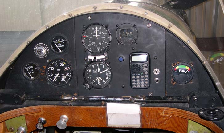
I used the old panel as a template to cut a new blank using my router table and a flush trim bit. A computer drawing package was used to lay out the new instrument and radio locations, and the full-size drawing was printed out on label stock and stuck to the panel face. Bolt holes were drilled, instrument holes were cut, the blank was varnished and painted, the gauges were reinstalled, and the radio mounted.
While the headset jacks and potentiometer were probably strong enough alone to hold the radio, I added two 3/16" bolts at the opposite corners. After installing matching Molex connector on the aircraft, carrying the power leads and PTT connections, the panel was installed and hooked up.
Drawbacks? The external volume control works well, but the audio fades away completely by the time the knob is turned down halfway. A 5K or even 1K pot might have been a better choice than my 10K unit. There's no access to the ICOM's side-mounted light switch, so I can't turn the light on. I considered adding a mechanism to work it, but since I'm flying as a Sport Pilot, the issue is pretty much moot. Sure, I can't take the radio out as a "walkaround" radio at air shows—but, heck, I could buy a second handheld with the $400 savings over a panel-mount radio.
"Full Metal Velcro" is cheaper, lighter, and smaller. Works for me….
Ron Wanttaja
As I mentioned in the text, I didn't use ICOM's headset
adaptor...I bought the appropriate plug and wired it to
panel-mount jacks.
I forgot one very important thing, though. The output
impedance of the ICOM at the 1/8" output jack is eight ohms....NOT
the 300 ohms of a standard aircraft headset!
In this condition, it will directly drive a standard set of ear
bud or Ipod headsets, but isn't the right impedance for aircraft
headsets. They'll work...but the volume will be down a
bit. Some headsets may not be able to handle the imbalance.
Now: One thing to keep in mind. The adaptors that
ICOM sells don't match the impedance, either! So the
setup above will give you no worse audio power than the standard
adaptor. I'm not sure of other radio's adaptors, but I don't
think any of them do impedance matching, either.
Getting the audio power back is relatively easy. All it
takes is audio transformer that costs about four bucks.
Radio Shack used to sell these, but Mouser.com sells a good unit
as well. Here's the basic schematic:
![]()
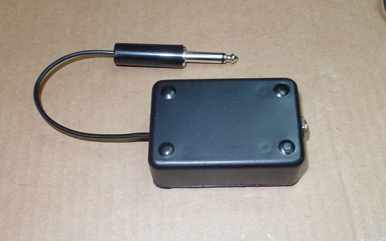
You can build this as a stand-alone box, as shown in the diagram
above and the photo below. The transformer and the jack are
installed inside a small box.
However, there are other options. You can use standard "ear
buds" directly for your headphones with the handheld. You'd
need to build a microphone holder, but that's a fairly small
job. See my Headset Options
page.
The OTHER thing you can do? Build the transformer right
into the panel, so that the headset jack is already converted to
300 ohm. No external adaptor needed.
Comments? Contact Ron Wanttaja .